Programming Cables
User Guide
© 2009-2019 Lattice Semiconductor Corp. All Lattice trademarks, registered trademarks, patents, and disclaimers are as listed at www.latticesemi.com/legal.
All other brand or product names are trademarks or registered trademarks of their respective holders. The specifications and information herein are subject to change without notice.
12 FPGA-UG-02042-26.2
7. Connecting the Programming Cable
The target board must be unpowered when connecting, disconnecting, or reconnecting the programming cable. Always
connect the programming cable’s GND pin (black wire) before connecting any other JTAG pins. Failure to follow these
procedures can result in damage to the target programmable device.
8. Programming Cable TRST Pin
Connecting the board TRST pin to the cable TRST pin is not recommended. Instead, connect the board TRST pin to Vcc.
If the board TRST pin is connected to the cable TRST pin, instruct ispVM/Diamond Programmer to drive the TRST pin
high.
To configure ispVM/Diamond Programmer to drive TRST pin high:
Select the Options menu item.
Select Cable and I/O Port Setup.
Select the TRST/Reset Pin Connected checkbox.
Select the Set High radio button.
If the proper option is not selected, the TRST pin is driven low by ispVM/Diamond Programmer. Consequently, the
BSCAN chain does not work because the chain is locked into RESET state.
9. Programming Cable ispEN Pin
The following pins should be grounded:
BSCAN pin of the 2000VE devices
ENABLE pin of MACH4A3/5-128/64, MACH4A3/5-64/64 and MACH4A3/5-256/128 devices.
However, you have the option of having the BSCAN and ENABLE pins driven by the ispEN pin from the cable. In this
case, ispVM/Diamond Programmer must be configured to drive the ispEN pin low as follows:
To configure ispVM/Diamond Programmer to drive ispEN pin low:
Select the Options menu item.
Select Cable and I/O Port Setup.
Select the ispEN/BSCAN Pin Connected checkbox.
Select the Set Low radio button.
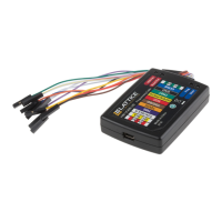
Each programming cable ships with two small connectors that help you keep the flywires organized. The following
manufacturer and part number is one possible source for equivalent connectors:
1 x 8 Connector (for example, Samtec SSQ-108-02-T-S)
2 x 5 Connector (for example, Samtec SSQ-105-02-T-D)
The programming cable flywire or headers are intended to connect to standard 100-mil spacing headers (pins spaced
0.100 inch apart). Lattice recommends a header with length of 0.243 inches or 6.17 mm. Though, headers of other
lengths may work equally well.
 Loading...