Programming Cables
User Guide
© 2009-2019 Lattice Semiconductor Corp. All Lattice trademarks, registered trademarks, patents, and disclaimers are as listed at www.latticesemi.com/legal.
All other brand or product names are trademarks or registered trademarks of their respective holders. The specifications and information herein are subject to change without notice.
FPGA-UG-02042-26.2 9
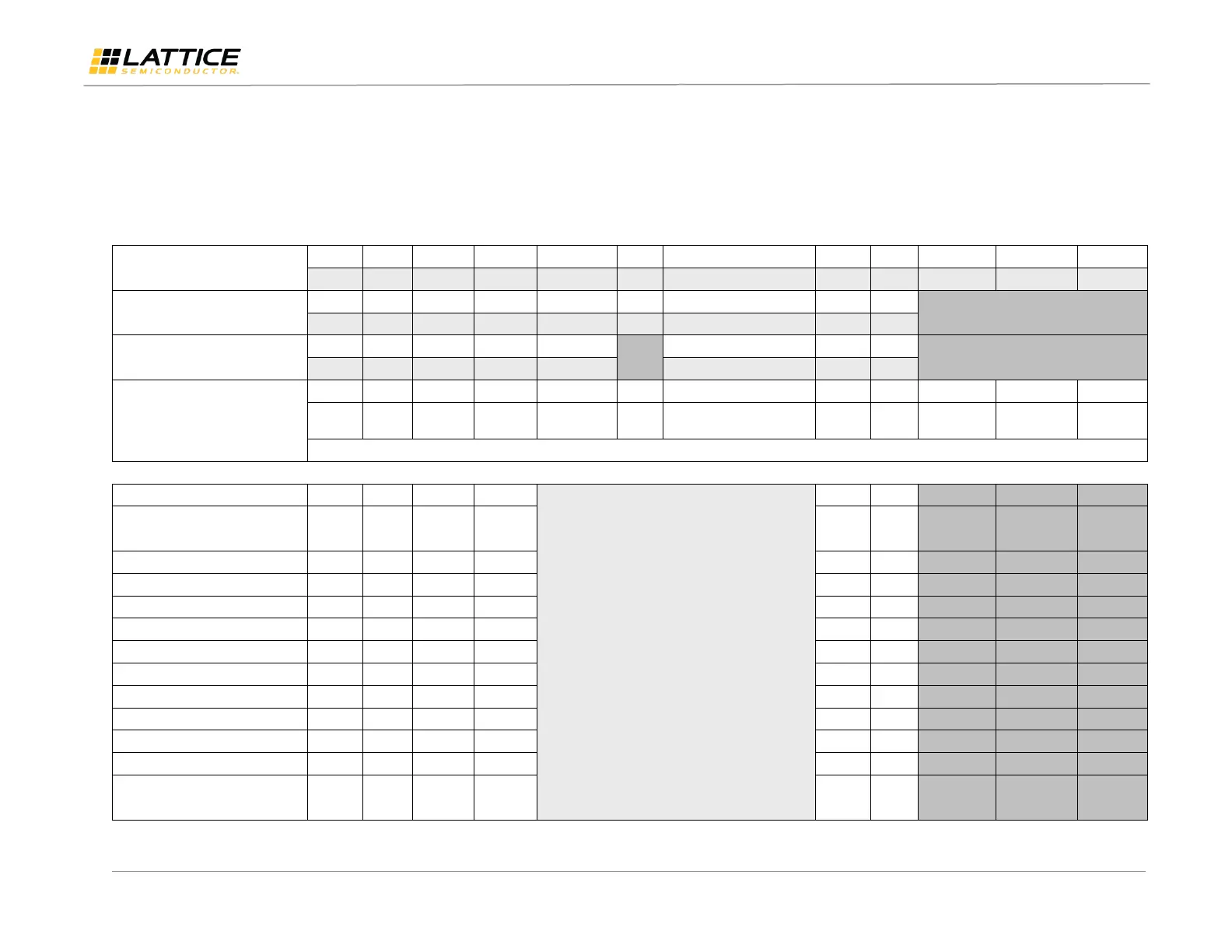
6. Programming Flywire and Connection Reference
Refer to Table 6.1 to identify, per Lattice device, how to connect various Lattice programming cable flywires. JTAG, SPI and I
2
C configuration ports are
unambiguously identified. Legacy cables and hardware are included for reference. In addition, various header configurations are tabulated.
Table 6.1. Pin and Cable Reference
Programming cable pin type
Target Board Recommendation
Connect the programming cable wires (above) to the corresponding device or header pins (below).
Optional connections to device ispEN, PROGRAMN,
INITN, DONE and/or TRST signals
(Define in Custom I/O settings in ispVM System
or Diamond Programmer software.
Not all devices have these pins available)
LatticeECP3™/LatticeECP2M™
LatticeECP2™/LatticeECP™/
LatticeEC™
MachXO2™/MachXO3™/MachXO3D™
ispMACH® 4000/ispMACH/ispLSI® 5000
ispPAC®/ispClock™ (Note 4)
Platform Manager™/Power Manager/
Power Manager II/Platform Manager II
(Note 4)
 Loading...