LAUNCH Injector Cleaner & Tester User’s Manual
3
Structure
Overview
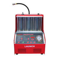
CNC series Injector Cleaner& Tester structure has been shown in Fig.01.
Fig.01
1-Return fuel connector; 2- Outlet fuel connector; 3- Top-supply fuel distributor assembly; 4- Measuring cup;
5- Control panel; 6- Socket for pulse signal cable; 7- Pressure gauge; 8- Power socket & Fuse; 9- Power switch
10- Tee joint; 11- Filter; 12- Fluid level switch; 13- Tank; 14- Return hose; 15- Fuel filler; 16- Pump; 17- Fluid
level indicator/Fuel draining hose; 18- Sliding curtain; 19- Ultrasonic cleaner; 20- drawer.
Note:
The illustrations in this manual may be slightly different from the actual product!
Control Panel
The control panel is shown in Fig.02 (Apart from models signs, the CNC-601A & CNC-602A & CNC-801A control panel is
identical.).
Fig.02
The control panel can be divided into five areas as shown in the following table:
Area Description
Item selection Select a function by pressing a[ ]key. The corresponding indicator will light.
Parameter selection Select a parameter by pressing a[ ]key. The corresponding indicator will light.
Parameter setting
After selecting function and parameter, the user can set the parameter value by
pressing[◄]/[►]key. ([►]key is for increasing, [◄]key is for decreasing.)
The set value will be displayed on LED screen.
System control
System control area below the Item selection & Parameter selection area, which
control the draining stop and run of the equipment.
System pressure control
System pressure control area below the Parameter setting area, which can adjust
the system pressure by pressing [increase pressure] / [decrease pressure] key.