11. DC SIGNAL CONDITIONER BOARD
The DC volts, DC amps and process transmitters utilize the DC signal conditioner board, which
needs to be configured via jumpers for the desired voltage or current range. All signal ranges
are factory calibrated with calibration factors stored in EEPROM on the signal conditioner
board. Instrument Setup Software recognizes the board and brings up the appropriate menu
items for it; however, it does not recognize the jumper settings. The excitation output can be
set to 5V @ 100 mA, 10V @ 120 mA, or 24V @ 50 mA via main board jumper settings. Please
see Section 14 of this manual.
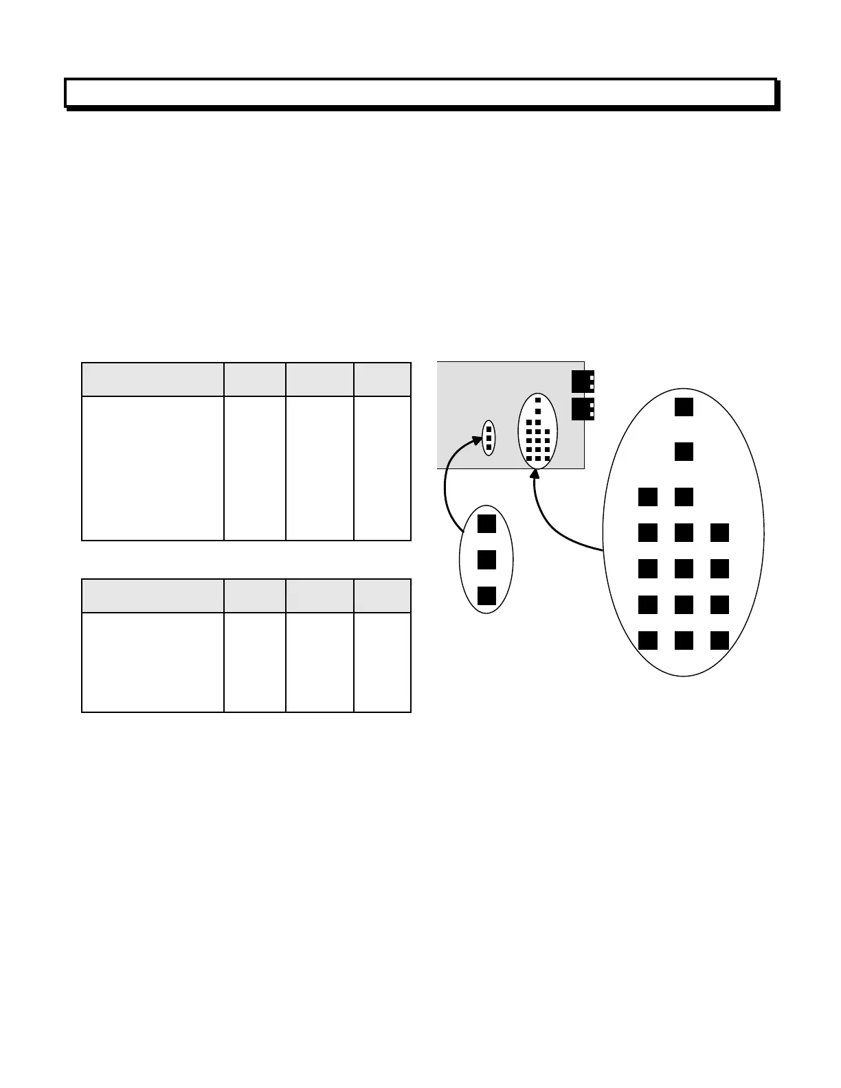
Board Revisions Q and R
1. Use 5 mm (0.2") jumpers for locations E1 designated by a capital letter.
2. Use 2.5 mm (0.1") jumpers for locations E2 and E3 designated by a lower case letter.
3. Store spare jumpers on an unused jumper post not associated with a capital letter.
For process & DC ratio, three scaling methods can be selected in Instrument Setup Software:
1) Scale and offset, 2) Coordinates of 2 points, and 3) Reading coordinates of 2 points, which
uses actual signals. Only menu items applicable to the selected method are presented. Full-
scale ranges are ±20000 counts. For resolution purposes, the 300V and 600V ranges are
2000V (100 mV/count), and the 5A range is 20A (1 mA/count).
For use with load cells, select 5V or 10V excitation, set Mode to Ratio, and set Range to 0.2V.
The transmitter will then use the excitation voltage as the reference for A-to-D conversion,
thereby correcting for any variations in excitation voltage. The excitation can drive four 350-
ohm load cells in parallel.