14. THERMOCOUPLE SIGNAL CONDITIONER BOARD
The thermocouple signal conditioner board can be configured via jumpers for either type J, K,
E, N thermocouples or type T, R, S thermocouples, and for upscale or downscale open sensor
indication. Instrument Setup Software recognizes the thermocouple board and will bring up the
appropriate menu items for it; however, it does not recognize jumper settings. For each jumper
selection, the thermocouple type, display in °C or °F, and resolution of 1°, 0.1° or 0.01° are
software selectable. High resolution should only be used for relative readings, not absolute
readings. Although available, 0.01° resolution is not recommended for thermocouples. Offset
adjustment is available for thermocouples and is normally set to 0000.0. If °C is selected,
entering an offset of 0273.2 will change the reading to Kelvin. If °F is selected, entering an
offset of 0459.7 will change the reading to Rankin.
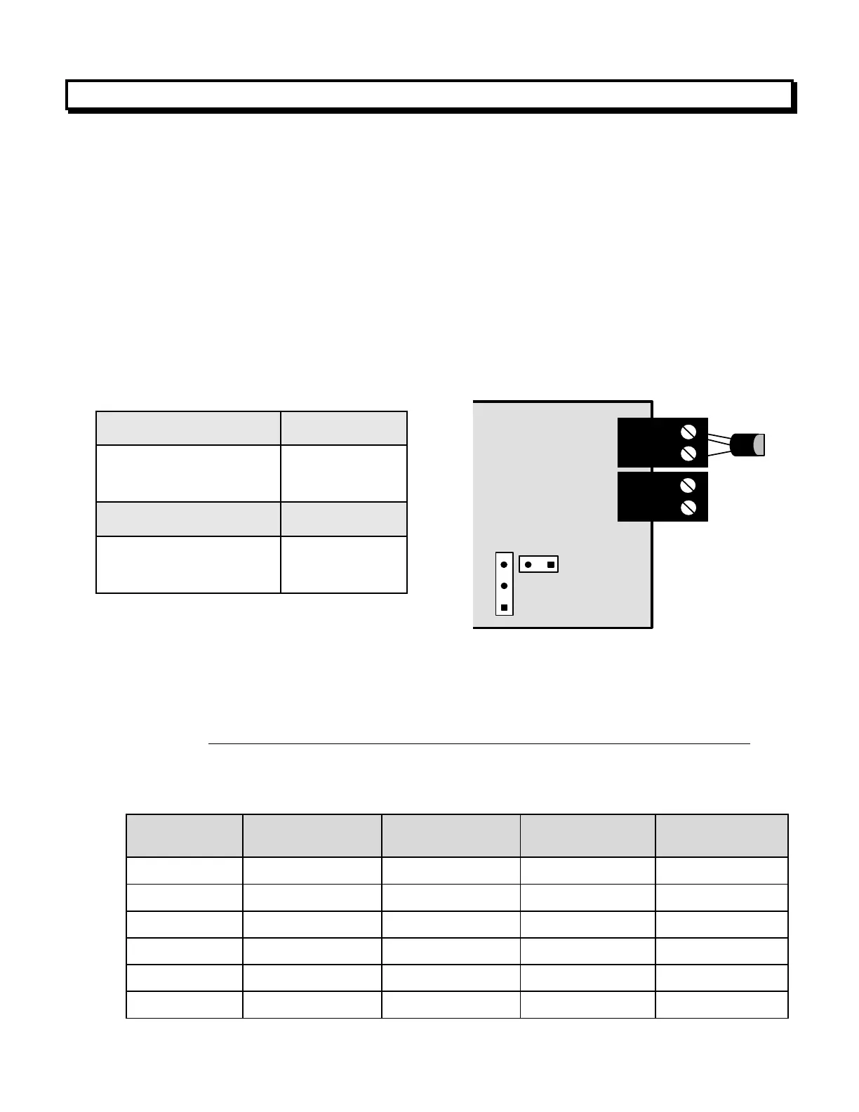
Board Revision A
1. Use 2.5 mm (0.1") jumpers.
2. Store spare jumpers on an unused jumper post.
The largest source of thermocouple reading errors are variations in the alloys used in
commercial thermocouple wires. Shown below are the American Limits of Error ASTM E230-
ANSI MC 96.1. These are the error limits imposed on manufacturers of thermocouple wire, not
error limits applicable to an instrument used with ideal thermocouple wire. The “Special Limit
of Error” applies to more expensive “Special Limits of Error” (SLE) thermocouple wire.