12. AC RMS SIGNAL CONDITIONER BOARD
Five RMS voltage and four RMS current ranges are jumper selectable, as is AC or DC coupling. All
signal ranges are factory calibrated with calibration factors stored in EEPROM on the signal condi-
tioner board. Instrument Setup Software recognizes the board and brings up the appropriate menu
items for it; however, it does not recognize the jumper settings. Ranges also have to be entered
manually.
Board Revision S
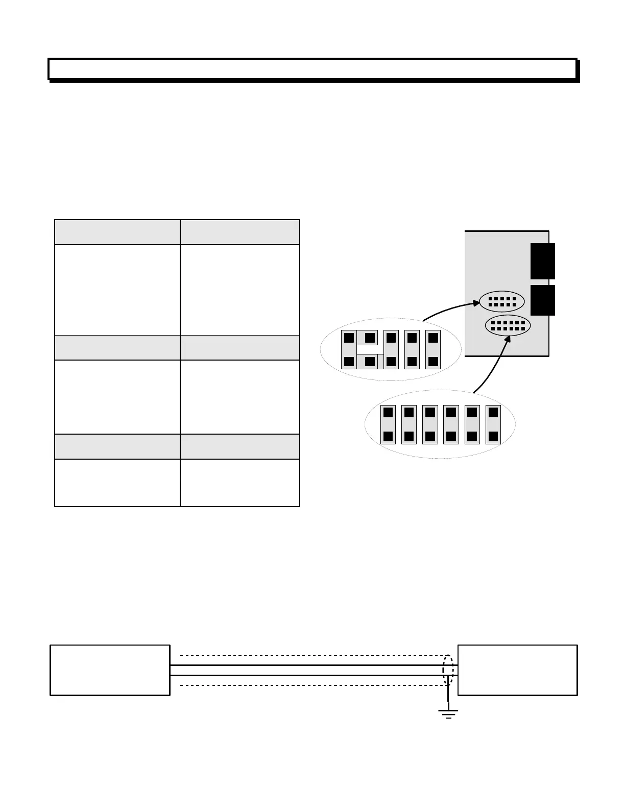
1. Use 2.5 mm (0.1") jumpers.
2. Store spare jumpers on an unused jumper post.
3. OK to remove the plug-in shield for jumper setting, but reinstall before closing the case.
To minimize noise pickup, the input signal wiring should utilize a shielded twisted pair, and the
shield should be connected to signal low at the rms board, as illustrated below. If signal low is
close to earth ground, such as within 2V, signal low can further be connected to earth ground.
The flexible noise shield may be removed for
jumper setting, but must then be reinstalled.