13. LOAD CELL SIGNAL CONDITIONER BOARD
The load cell signal conditioner board offers sensitivity to ±20 mV full-scale and 4 or 6-wire
load cell connection. This board needs to be configured via jumpers for the desired full-scale
voltage range. All ranges are factory calibrated with calibration factors stored in EEPROM.
Instrument Setup Software recognizes the board and will bring up the appropriate menu items
for it; however, it does not recognize the jumper settings. The ranges also have to be selected
in Instrument Setup software. The excitation output can be set to 5V @ 100 mA, 10V @ 120
mA, or 24V @ 50 mA via main board jumper settings. Please see Section 14 of this manual.
Operation is ratiometric, with automatic compensation for changes in excitation voltage.
For DC microvolt applications, a scale factor of 1 and an offset of 0 are used for direct read-
ings in microvolts or millivolts. Decimal point selection does not affect the displayed digits. For
example, 20 mV can be transmitted as 20.000 mV or 20000 µV. The decimal point is set
separately.
For load cell applications, three scaling methods can be selected in Instrument Setup
Software: 1) Scale and offset, 2) Coordinates of 2 points, and 3) Reading coordinates of 2
points, which uses actual signals. Only menu items applicable to the selected scaling method
will be presented.
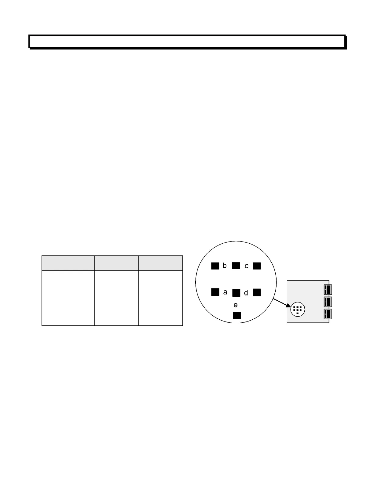
1. Use 2.5 mm (0.1") jumpers.
2. Store spare jumpers on an unused jumper post.