41
NOPULL
TM
STARTER SYSTEM
B. Red ashing of the battery indicator LED indicates that battery voltage is too low and needs to be
charged.
C. Green ashing of the battery indicator LED indicates that a short circuit occurs in the electric starter.
Check the electric motor and the motor drive lines as below:
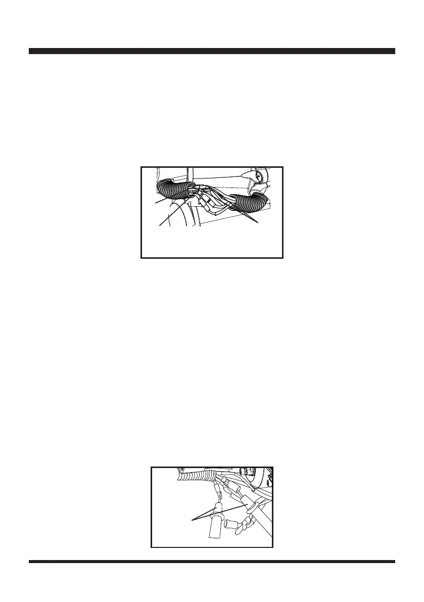
Open the corrugated pipe and disconnect the male and female terminals of the motor drive lines (blue)
(Fig. 82). Press the start button and check if the LED ashes green. LED does not ash - the short
circuit occurs in the electric motor or the motor drive lines of the engine. LED ashes green - the short
circuit occurs in the motor drive lines of the handle.
D. Alternate red and green ashing of the battery indicator LED indicates that an overcurrent occurs in
the electric starter part. Check if the engine is stuck and cannot be rotated smoothly. Check if there
is any foreign matter, such as metal, magnetized on the ywheel.
E. If the battery indicator LED is continuously on, check that if an open circuit occurs from the PCB
output to the motor connecting line.
When pressing the start button and the LED is continuously on, test the voltage output in the motor
drive lines using the DC voltage stall of multi-meter (Fig. 83).
If there is voltage output, the possible causes are as below:
1). The electric motor has broken down;
2). The motor drive lines of the engine have detached from their welding position to the electric
motor;
3). There is loose or failed contact in the connection from the motor drive lines of the engine to the
male and female terminals in the corrugated pipe buckle.
If there is no voltage output, the possible causes are as below:
1). The motor drive lines of the handle have detached from their welding position to the PCB;
2). There is loose or failed contact in the connection from the motor drive lines of the handle to the
male and female terminals in the corrugated pipe buckle.
Fig. 82
Red (+)
Black (-)
Terminals of
motor drive
lines (Blue)
Fig. 83
Test by
multi-meter

 Loading...