F730 0
F733 0
F734 0
F735 0
F736 1
● Communication Parameters
F800 3
F801 1
F802 0
F803 0
F805 0.00
F806 0
F811 0
F812 0.0
F813 100
F814 60.0
F829 0
F870 0
F871 0
F875 0
F876 0
F877 0
F878 0
F879 0
F880 0
F890 0
F891 0
F892 0
F893 0
F894 0
● Unused Parameter
F910 100
F911 0.0
*1: Default sett
ing of the parameter differs by each inverter capacity. Refer to
"Default settings by Inverter Rating" table below for actual values.
*2: Unit displayed may be selected by parameter F701 (Unit selection).
*3: Always implement DC reactor (optional) when setting parameter F627
(Undervoltage trip/alarm selection) to "2 (detection level below 50%)."
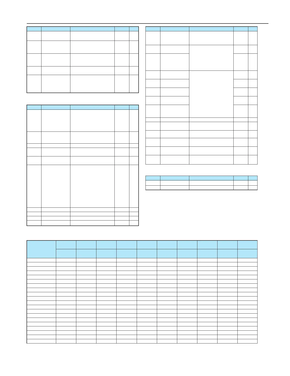
Title Function Adjustment range
Default setting
Note
Panel operation
prohibition (FC)
Prohibition of panel
operation
(RUN/STOP keys)
Prohibition of panel
emergency stop
operation
Prohibition of panel
reset operation
Prohibition of
change of
CMod/FMod during
operation
0: Permitted,
1: Prohibited
0: Permitted,
1: Prohibited
0: Permitted,
1: Prohibited
0: Permitted,
1: Prohibited
0: Permitted,
1: Prohibited
Communication
band speed
Parity (Common serial)
Inverter number
Communication
error trip time
Communication
waiting time
Setting of master
and slave inverters
for communications
between inverters
Point # 1 setting
Point # 1 frequency
Point # 2 setting
Point # 2 frequency
0: 1200bps
1: 2400bps
2: 4800bps
3: 9600bps
4: 19200bps
0: NON (No parity)
1: EVEN (Even parity)
2: ODD (Odd parity)
0-255
0: Disabled (*)
1-100 (s)
0.00-2.00 (s)
0:
Slave inverter (0 Hz command issued in
case the master inverter fails)
1:
Slave inverter (Operation continued
in case the master inverter fails)
2:
Slave inverter (Emergency stop tripping
in case the master inverter fails)
3: Master inverter (transmission
of frequency commands)
4: Master inverter (transmission
of output frequency signals)
0-100 (%)
0-500.0 (Hz)
0-100 (%)
0-500.0 (Hz)
Title Function Adjustment range
Default setting
Note
Title Function Adjustment range
Default setting
Note
Selection of
communication
protocol
Block write data 1
Block write data 2
Block read data 1
Block read data 2
Block read data 3
Block read data 4
Block read data 5
Free notes
Parameters for
option 1
Parameters for
option 2
Parameters for
option 3
Parameters for
option 4
Parameters for
option 5
0: Sumitomo Inverter protocol
1: Modbus RTU protocol
0: No selection
1: Command information 1
2: Command information 2
3: Frequency command
4:
Output data on the terminal board
5:
Analog output for communications
0: No selection
1: Status information
2: Output frequency
3: Output current
4: Output voltage
5: Alarm information
6: PID feedback value
7: Input terminal board monitor
8:
Output terminal board monitor
9: VRF terminal board monitor
10: VRF2 terminal board monitor
0-65535
0-65535
0-65535
0-65535
0-65535
0-65535
Title Function Adjustment range
Default setting
Note
-
-
Do not change
Do not change
ub/F172 F308 F309 F401 F402 F415 F416 F417 F494 F626
(%) (:) (kW) (%) (%) (A) (%) (r/min) (%)
●Default Settings by Inverter Rating
HF321S-A20 6.0 400.0 0.2 100 7.0 1.5 85 1750 90 134
HF321S-A40 6.0 200.0 0.2 80 6.4 2.3 84 1735 90 134
HF321S-A75 6.0 200.0 0.3 70 4.7 3.9 75 1740 80 134
HF321S-1A5 6.0 80.0 0.3 80 5.0 6.6 55 1720 70 134
HF321S-2A2 5.0 70.0 0.4 75 3.8 9.3 55 1745 70 134
HF3212-A20 6.0 400.0 0.2 100 7.0 1.5 85 1750 90 134
HF3212-A40 6.0 200.0 0.2 80 6.4 2.3 84 1735 90 134
HF3212-A75 6.0 200.0 0.3 70 4.7 3.9 75 1740 80 134
HF3212-1A5 6.0 80.0 0.3 80 5.0 6.6 55 1720 70 134
HF3212-2A2 5.0 70.0 0.4 75 3.8 9.3 55 1745 70 134
HF3212-3A7 5.0 40.0 0.6 80 3.6 14.8 44 1740 70 134
HF3212-5A5 4.0 20.0 1.5 75 3.8 21.5 42 1750 70 134
HF3212-7A5 3.0 20.0 1.5 75 4.0 29.1 43 1755 70 134
HF3214-A40 6.0 750.0 0.2 76 6.4 1.2 82 1735 90 140
HF3214-A75 6.0 750.0 0.3 70 4.2 1.9 75 1740 80 140
HF3214-1A5 6.0 400.0 0.3 80 5.4 3.3 55 1720 70 140
HF3214-2A2 5.0 250.0 0.4 75 3.5 4.7 55 1745 70 140
HF3214-3A7 5.0 160.0 0.6 85 3.2 7.4 44 1740 70 140
HF3214-5A5 4.0 83.0 1.2 65 3.9 10.7 42 1750 70 140
HF3214-7A5 3.0 83.0 1.2 75 3.6 14.6 43 1755 70 140
Inverter type
Torque
boost
Dynamic braking
resistance
Dynamic braking
resistor capacity
Slip frequency
gain
Motor constant #1
(primary resistance)
Motor rated
current
Motor no-load
current
Motor rated
speed
Motor adjustment
factor
Over-voltage stall
protection level
 Loading...