CS-D808 Closed Loop Stepper Drive User Manual
Page | 8
GND
A+
A-
+Vdc
Encoder Signal
Connector
1
5
6
Power &
Motor Connector
Controller
Black
Red
Control Signal
Connector
4
PUL+
1
DIR+ 3
PUL-
DIR-
2
4
ENA+ 5
ENA-
6
5V
Step
Direction
Enable
EA+: BLK EA-: BLU
EB+: YEL EB-: GRN
+5V: RED GND: WHT
Status Signal
Connector
30-72VDC recommended,
leaving rooms for voltage fluctuation
and back EMF of the motor
2
Encoder
Extension Cable*
Encoder
Cable
*must be used
Power
Extension Cable
Power
Cable
3
B+
B-
Yellow/Green
Blue
CS-D808
Fault
5V
ALM+ 1
2
ALM-
In-Positiion
Pend+ 1
2
Pend-
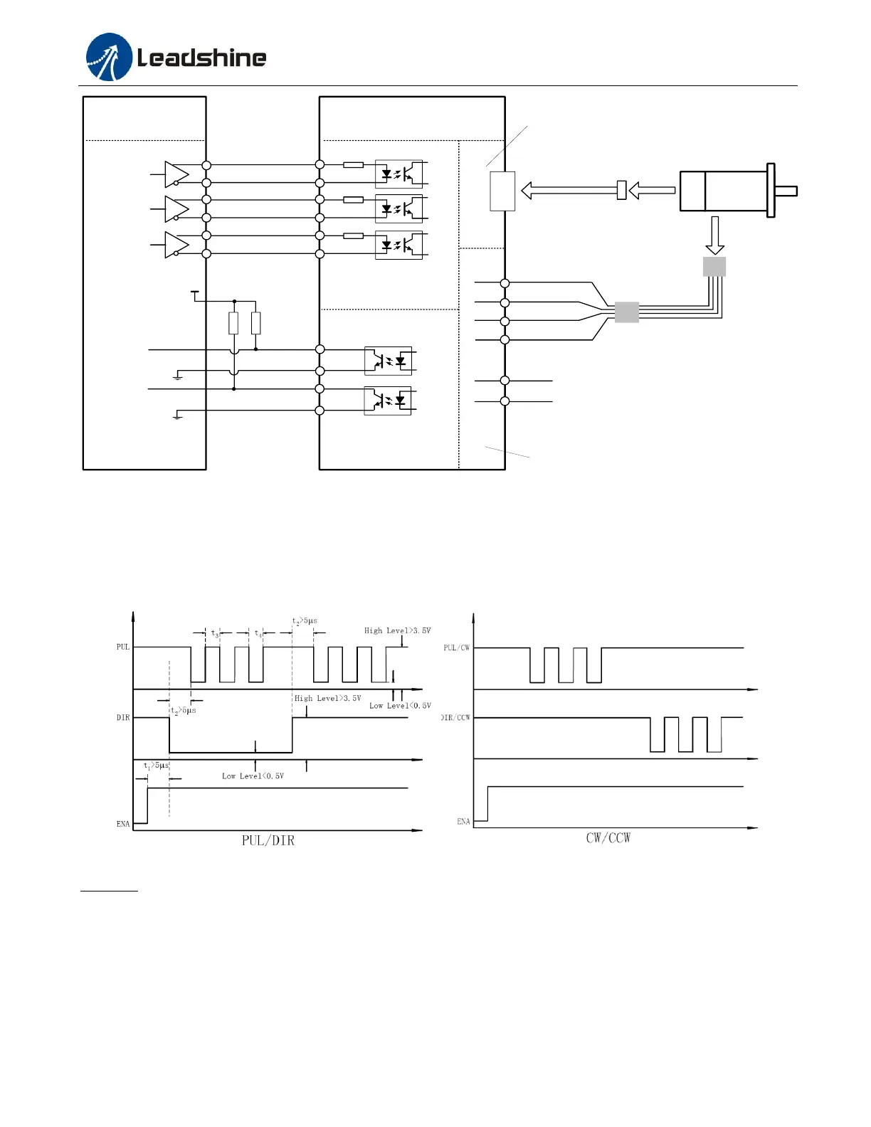
Figure 6: Typical connection
8. Sequence Chart of Control Signals
In order to avoid some fault operations and deviations, PUL, DIR and ENA should abide by some rules, shown as
following diagram:
Figure 7: Sequence chart of control signals
Remark:
a) t1: ENA must be ahead of DIR by at least 5s. Usually, ENA+ and ENA- are NC (not connected). See
“Connector P1 Configurations” for more information.
b) t2: DIR must be ahead of PUL effective edge by 5s to ensure correct direction;
c) t3: Pulse width not less than 2.5s;
d) t4: Low level width not less than 2.5s.