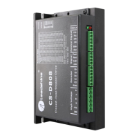
CS-D808 Closed Loop Stepper Drive User Manual
Table of Contents
1. Introduction.................................................................................................................................................................. 1
1.1 Features ................................................................................................................................................................ 1
1.2 Applications ......................................................................................................................................................... 1
2. Specifications ................................................................................................................................................................ 1
2.1 Electrical Specifications ...................................................................................................................................... 1
2.2 Environment ........................................................................................................................................................ 2
2.3 Mechanical Specifications ................................................................................................................................... 2
2.4 Heat Dissipation................................................................................................................................................... 2
3. Connections and LED Indication ............................................................................................................................... 3
3.1 Connector P1 & P2– Control Input and Output Connections .............................................................................. 3
3.1.1 Pin Assignments of P1 & P2 ..................................................................................................................... 3
3.1.2 Typical Control and Fault Output Connections ........................................................................................ 4
3.2 Connector P3 - Encoder Connection.................................................................................................................... 4
3.3 Connector P4 - Motor and Power Supply Connection ......................................................................................... 5
3.4 Connector P5 – RS232 Connection ..................................................................................................................... 5
3.5 LED Light Indication ........................................................................................................................................... 5
4. Motor Selection ............................................................................................................................................................ 5
5. Power Supply Selection ............................................................................................................................................... 5
5.1 Regulated or Unregulated Power Supply ............................................................................................................. 6
5.2 Power Supply Sharing ......................................................................................................................................... 6
5.3 Selecting Supply Voltage ..................................................................................................................................... 6
6. DIP Switch Configurations ......................................................................................................................................... 6
6.1 Microstep Resolution (SW1-SW4) ...................................................................................................................... 7
6.2 Other DIP Switch Settings (SW5-SW6) .............................................................................................................. 7
7. Typical Connection ...................................................................................................................................................... 7
8. Sequence Chart of Control Signals ............................................................................................................................ 8
9. Protection Functions .................................................................................................................................................... 9
10. Software Configuration ............................................................................................................................................. 9
11. Accessories .................................................................................................................................................................. 9
12. Troubleshooting ......................................................................................................................................................... 9
13. Warranty .................................................................................................................................................................. 11
Appendix A. Leadshine CS-D808 Compatible Stepper Motors .............................................................................. 12
Appendix B. Leadshine CS-D808 Compatible Power Supplies .............................................................................. 13