3
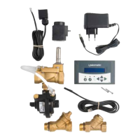
VALVE UNIT
INSTALLATION
• Flawless operation can only be guaranteed if the device has been installed
following the installation instructions.
• The warranty will become invalid if the device is installed incorrectly or removed.
The valve unit is a precision tool that must not be modified or removed.
• Make sure that the installer has documented the details of the installation in
the Installation certificate before you approve the installation. The installation
certificate can be found on the last page of this document.
HOW DOES LEAKOMATIC WORK?
The valve unit is installed in the inflow pipes and it protects the pressurised piping
system. The measuring unit constantly analyses water consumption by measuring
the amount of water that flows through the device. When the display is out of
power, the valve is open. If the valve is closed and a power failure occurs, the valve
will open.
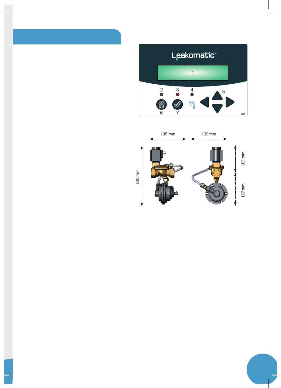
USER MANUAL
CONTROL UNIT
1. Screen
2. Mode indicator
3. Alarm/warning light
4. Flow indicator
5. Arrows
6. Mode button
7. Clear button