There are seven resistance (SNs 23-003 through
024) or capacitance fuel quantity probes in-
stalled. One fuel probe is located in each tip
tank and in the fuselage tank. Each wing tank
has two probes wired in parallel. The inboard
probe in the left wing contains a density com-
pensator which adjusts quantity readings for
all switch selections for fuel density change.
Each probe uses an electrical resistance or ca-
pacitance measuring system to sense the fuel
level. It then transmits an electrical signal to
the cockpit indicator where it is read as pounds
✕ 1,000 on the gage.
NOTE
The total position of the selector
switch should be used for flight plan-
ning purposes due to tolerances in the
individual tank quantity readings.
The quantity indicating system is set
to indicate properly in level flight.
On all Learjets except SNs 23-003 through
23-014, one or two LOW FUEL lights are ac-
tuated by each wing tank fuel low-level float
switch when fuel quantity in either tank is ap-
proximately 450 pounds. On airplanes with-
out a glareshield panel, left and right LOW
FUEL lights (see Figure 5A-5) are located on
the fuel panel. On airplanes with a glareshield
warning panel, a single LOW FUEL light (see
“Annunciator Panel” section) will illuminate
when either wing fuel quantity is low.
When the fuel quantity gage indi-
cates 600 pounds or less remaining
in either wing tank, prolonged noseup
attitude of 10° or more may cause
fuel to be trapped in the aft area of
the wing tank outboard of the wheel
well. Fuel starvation and engine
flameout may occur. Reducing pitch
attitude and thrust to the minimum
required will prevent this situation.
Learjets SNs 23-015 through 23-089 use 115
VAC for the fuel quantity indicating system.
All other Learjets use 28 VDC.
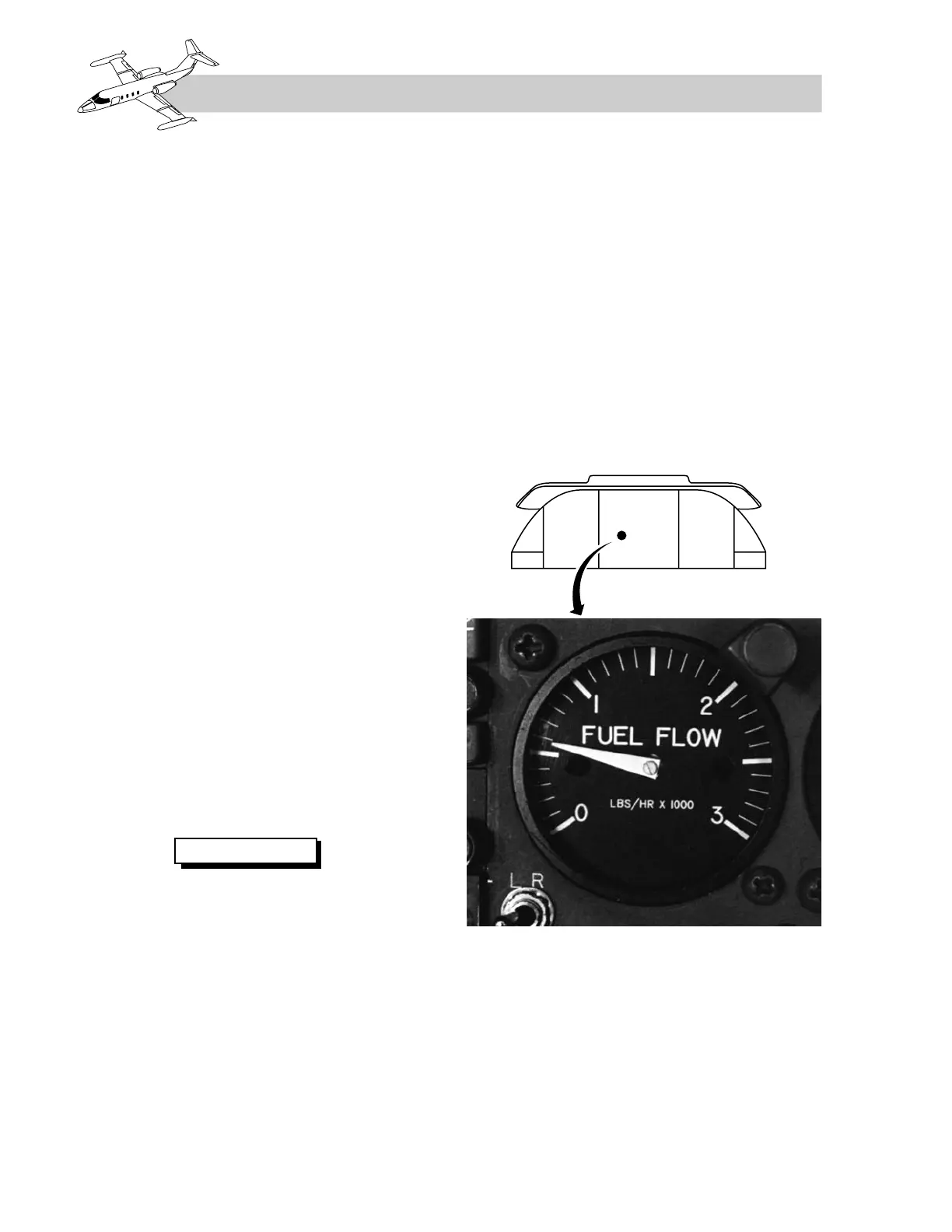
FUEL FLOW
INDICATING SYSTEM
A fuel flow indicator provides a readout in
pounds of fuel flow per hour (Figure 5A-6).
Airplanes SNs 23-003 through 23-069 have a
single indicator with two needles labeled “L”
and “R,” which uses 26 VAC. All other Learjets
use a single 28-VDC-powered indicator with
one needle and a selector switch labeled “L–R”
adjacent to the indicator to select either engine.
The optional fuel counter (see Figure 5A-5)
located on the fuel control panel provides a
four-digit readout (in pounds of fuel consumed
by both engines) and uses DC power. It should
be reset to zero using the reset button adjacent
to the counter before starting the first engine.