EMERGENCY MODES
In emergency operation, three different modes
of inverter operation are possible: (1) With a
primary inverter failure, the standby inverter,
through a switching network, automatically
provides power to the primary 115-VAC and
26-VAC buses. Secondary inverter operation
is not affected. (2) With a secondary inverter
failure, the standby inverter, through a switch-
ing network, automatically provides power to
the secondary 115-VAC and 26-VAC buses.
Primary inverter operation is not affected. (3)
With both primary and secondary inverters
failed, the standby inverter, through a switch-
ing network, automatically provides power to
the pilot’s 115-VAC and 26-VAC buses and the
copilot’s 26-VAC bus. Operation of the radar
is not affected by any of the emergency modes.
With a primary and secondary inverter failure,
the copilot’s 115-VAC bus is deenergized,
and, because this bus powers the pilot’s RMI
card, it ,too, is inoperative.
EMERGENCY BATTERY
SYSTEM
An emergency battery is probably installed
in most model 23 airplanes. SNs 24-100
through 24-129 have an auxiliary battery in-
stalled. On all other airplanes, an optional
emergency battery is available.
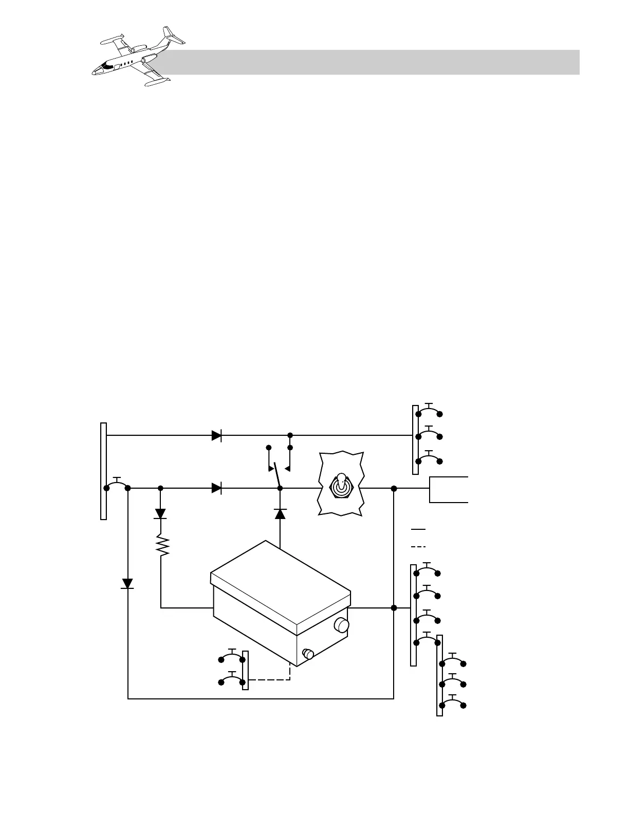
Auxiliary Battery System—
SNs 24-100 through 24-129
Auxiliary battery power (Figure 2A-20) is
supplied by a 2.6-ampere-hour, 25-volt, nickel-
cadmium dry-cell battery. The battery, in-
stalled beneath the divan seat, consists of a
steel case containing 20 cells and a 50-VA in-
verter. The inverter provides 115-VAC, 400-
Hz, single-phase power. The battery receives
a trickle charge from the battery charging bus.
Power is controlled by an ON–OFF switch
and a momentary switch.
2A-21
FOR TRAINING PURPOSES ONLY