The No. 1 bearing housing is on the aft side
of the inner shell of the front frame. The bear-
ing is a spherical, self-aligning roller bearing
designed to absorb any misalignment of the
forward compressor shaft. Three of the front
frame struts are oversized and contain the No.
1 bearing service lines. The ten o’clock strut
houses the bearing oil supply tube, the two o’-
clock strut houses a sump vent tube, and the
six o’ clock strut houses an oil scavenge tube.
A variable inlet guide vane is mounted aft of
each of the front frame struts. The outer ends
of the movement of the actuator ring will cause
movement of the inlet guide vanes to direct air-
flow to the first-stage rotor blades at the proper
angle. The actuator ring and inlet guide vanes
are positioned by the variable geometry actu-
ators, which utilize high-pressure fuel from the
engine fuel control unit.
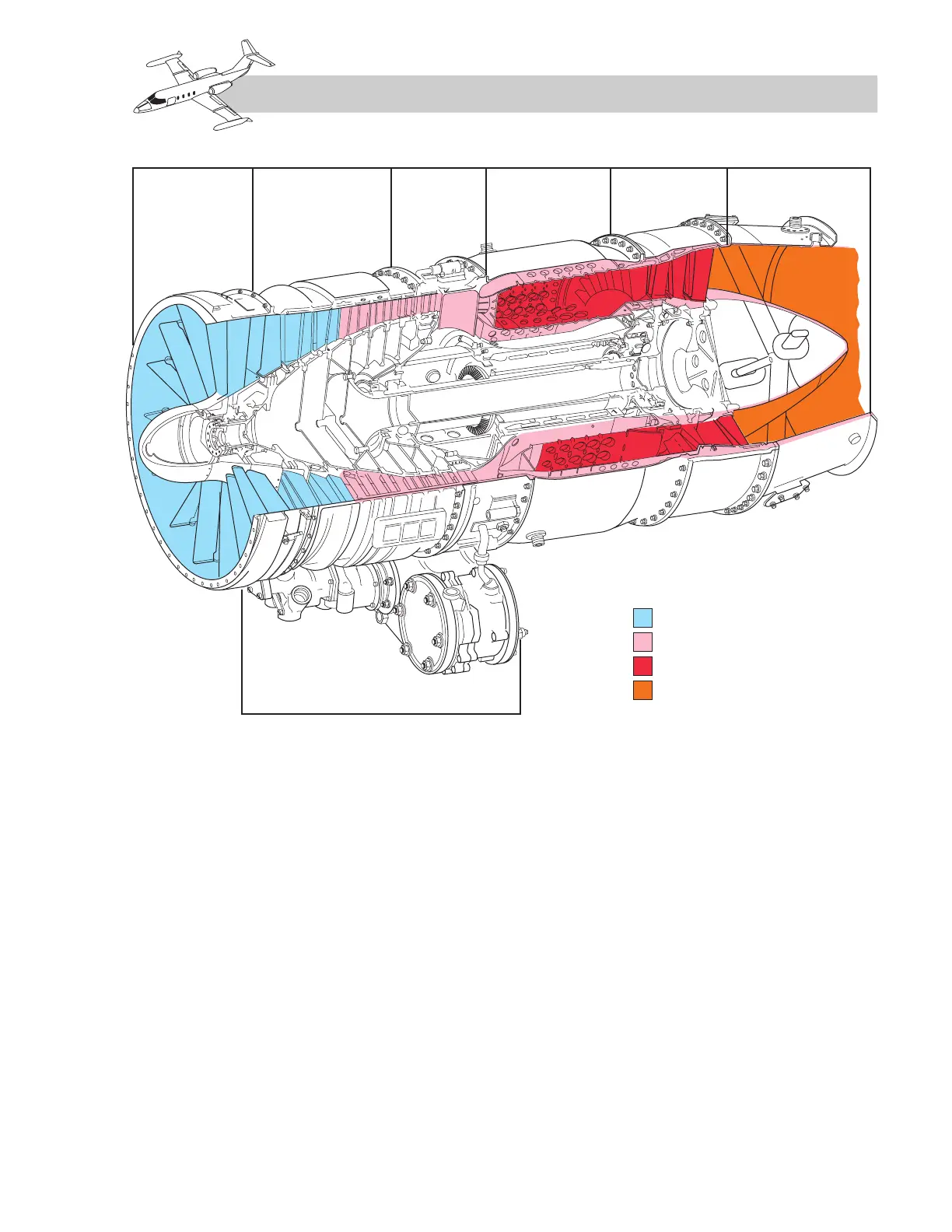
Compressor
The compressor (Figure 7-3) is an eight-stage
axial-flow unit consisting of rotors and stators.
It functions to increase the pressure of the
inlet air and direct the airflow rearward. The
stator casing assembly which surrounds the
compressor rotor assembly consists of a com-
pressor casing upper half and lower half with
seven stages of stator vanes. The compressor
casing is an annular chromalloy component,
split and flanged along the horizontal cen-
terline and reinforced externally
by integral
7-3
FOR TRAINING PURPOSES ONLY