9/15
CONTENTS
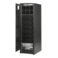
10’’ PDUs
19’’ PDUs
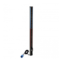
Zero-U PDUs
Data sheet: S000093176EN-05 Updated: 29/03/2018 Created: 25/10/2016
Cat. Nos: 6 468 00/01/05/06/07/09/10/11/12/13/14/15/18/19/
20/21/22/23/24/30/31/32/33/35/36/40/41/42/43/44/
45/50/51/52/53/54/56/57/59/60/61/65/70/75/90/92/94/
95/97/98/99
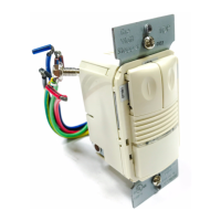
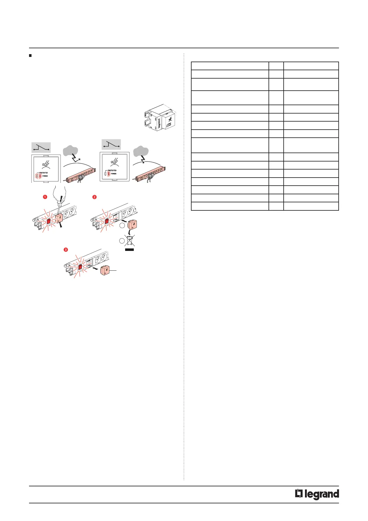
3.5 Surge protection and replacement module
Protection between Line and neutral of socket outlets connected
downstream against overloads generated by the electrical network
upstream of the surge protective device by creating a discharge current
on the network and/or earthing link.
To be used in combination with a voltage surge protector installed in
the panel..
P
R
O
T
E
C
T
ED
PO
W
ER
PR
O
TE
C
TE
D
P
O
W
E
R
B
A
ON
P
ROTECTED
P
O
WER
P
ROTECTED
P
O
WER
ON
6 468 97
ON
Operation
• Surge protective devices are designed to limit transient overvoltages
of atmospheric and industrial origin.
• They have a certain capacity to absorb energy and age with each
operation; it is therefore normal for them to be out-ot-order after a
certain number of operations. The imminent out-of-order status is
signalled and the draw-out module should be replaced.
• Surge protective devices are designed to be installed at use points and
are to be used in combination with the installation’s original modular
protection.
• They are not designed to provide sole protection for an installation
in a building likely to be hit by direct lightning strikes (e. g. buildings
equipped with lightning arresters). This would immediately put the
device out-of-order by exceeding its maximum discharge capacity.
• Overloads of atmospheric origin occur between the active wires and
the earth. They are highly charged and uncontrolled.
• Overloads of industrial origin occur between the active wires (L+N)
and are not so highly charged.
• The surge protective devices are equipped with an operation indicator
light (to be checked on a regular basis):
- Mains supply present and green indicator light on: operational
protection.
- Mains supply present and red indicator light on: change the module.
- Once the draw-out module is out-of-order the installation is no longer
protected but remains powered (including the withdrawn module).
Technical data
Number of poles 2
Neutral system TT - TNS
Mode of protection MCB C16 and/or MCBO
300mA
Maximum continuous operating voltage U
C LN & N/PE 255V
L/PE 440V
Nominal sysem voltage U 230 VAC
Assigned current of load I
L 16A
Frequency F 50/60 Hz
Open cicuit voltage U
OC 10 kV
Voltage protection level U
P L/N 1kV
L/PE & N/PE 1,2kV
Temporary overvoltage test value U
T 441V
Nominal discharge current In 5kA
Maximum discharge current Imax 10 kA
Current factor k 1.6
Type Type 2 (T2) _ Type 3 (T3)
Location Indoor
Temperature and humidity range Normal range : -5°C : +40°C
Mechanical characteristics
IP 20
Cleaning
Without cleaning
Replaceable element: Cassette Reference 6 468 9
Conformity
In compliance with the standard NF EN 61643-11 : 2014