EasyManua.ls Logo

LEGRAND DPX3 160 User Manual

LEGRAND DPX3 160
6 pages
To Next Page IconTo Next Page
Page #1 background imageLoading...
Page #1 background image
134
DPX
3
160 and 250 common auxiliaries and accessories
Pack Cat.Nos
Auxiliaries
Auxiliary contacts
1
4 210 10
1 N/C + 1 N/O auxiliary contact for rotary handles
1
4 210 11
Auxiliary contact or fault signalling contact
1
4 210 48
Signalling contact plugged-in / drawn-out (for DPX
3
plug-in version)
Shunt releases
1
4 210 12
12 VA/ =
1
4 210 13
24 VA/ =
1
4 210 14
48 VA/ =
1
4 210 15
110 -13 0 VA
1
4 210 16
200-277 VA
1
4 210 17
380-480 VA
Undervoltage releases
1
4 210 18
12 VA/ =
1
4 210 19
24 VA/ =
1
4 210 20
48 VA/ =
1
4 210 21
110 -13 0 VA/ =
1
4 210 22
200-240 VA
1
4 210 23
277 VA
1
4 210 24
380 -415 VA
1
4 210 25
440-480 VA
Locking accessory
1
4 210 49
Padlock for locking in "open" position
Pack Cat.Nos
Supply invertor type
Plate for mounting and interlocking of 2 DPX
3
For 2 DPX
3
160 or 2 DPX
3
250 or 1 DPX
3
160 and
1 DPX
3
250
1
4 210 58
For fixed version
1
4 210 59
For plug-in and draw-out version
Rotary handles
Direct on DPX
1
4 210 00
Standard handle for thermal magnetic DPX
3
without
earth leakage module
1
4 210 01
Standard handle for electronic DPX
3
and/or with
earth leakage module
1
4 210 02
Handle for emergency use for thermal magnetic
DPX
3
without earth leakage module
1
4 210 03
Handle for emergency use for electronic DPX
3
and/
or with earth leakage module
Vari-depth handles
For all version of DPX
3
1
4 210 04
Standard handle
1
4 210 05
Handle for emergency use
Locking accessories
1
4 210 06
Key barrel and flat key N° ABA90GEL6149
for direct handle
1
4 210 07
Key barrel and star key N° HBA90GPS6149
for direct handle
1
4 210 08
Key barrel and flat key N° ABA90GEL6149
for vari-depth handle
1
4 210 09
Key barrel and star key N° HBA90GPS6149
for vari-depth handle
Motor-driven handles
Motor operators 24 to 230 VA/ =
1
4 210 60
Side motor operator
1
4 210 61
Front motor operator
Locking accessories
1
4 210 62
Key barrel and flat key N° ABA90GEL6149
for front motor operator
1
4 210 63
Key barrel and star key N° HBA90GPS6149
for front motor operator
1
4 210 64
Padlock for front motor operator
1
4 210 65
Key barrel and flat key N° ABA90GEL6149
for side motor operator
1
4 210 66
Key barrel and star key N° HBA90GPS6149
for side motor operator
1
4 210 67
Padlock for side motor operator
4 210 58
4 210 10 4 210 11
4 210 16 4 210 224 210 00
RS 485 communication interface
p. 146

Other manuals for LEGRAND DPX3 160

Question and Answer IconNeed help?

Do you have a question about the LEGRAND DPX3 160 and is the answer not in the manual?

LEGRAND DPX3 160 Specifications

General IconGeneral
BrandLEGRAND
ModelDPX3 160
CategoryRelays
LanguageEnglish

Summary

Supply Invertor Type Accessories

Supply Invertor Plate

Plate for mounting and interlocking of 2 DPX3 breakers.

Rotary Handles

Direct on DPX Handles

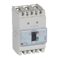
Standard handles for thermal magnetic and electronic DPX³.

Vari-depth Handles

Handles for DPX³ breakers with vari-depth installation.

Locking Accessories for Handles

Key Barrels and Keys

Key barrels with flat or star keys for direct/vari-depth handles.

Padlock for Locking

Padlock accessory for locking in the 'open' position.

Motor-Driven Handles

Motor Operators

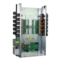
Motor operators for remote control of DPX³ breakers.

Locking Accessories for Motor Operators

Key barrels and padlocks for motor-driven handles.

Auxiliaries

Auxiliary Contacts

N/C + N/O auxiliary contacts and fault signalling contacts.

Shunt Releases

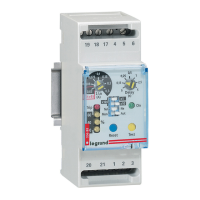
Releases for remote tripping at specified voltages.

Undervoltage Releases

Releases for tripping due to voltage drops.

Locking Accessory

Padlock for locking in 'open' position.

Installation Principles Diagrams

Auxiliaries Mounting

Diagram showing mounting of auxiliaries like shunt and undervoltage releases.

Rotary Handle Installation

Diagram illustrating direct rotary handle installation.

Plug-in Version

Diagram showing the principle of plug-in version installation.

Motor-Driven Handle Installation

Diagrams for side and front mounting motor-driven handles.

Supply Invertor Type Installation

Diagram illustrating the supply invertor type installation.

Accessory Identification and Function

Auxiliary and Release Legends

Legends for Undervoltage release (UVR), Shunt trip (ST), and delayed releases (UVR/EM).

DPX³ 160 - DPX³ 250 Accessory Table

Table showing compatibility of ST, UVR, and ECT R accessories with 3P/4P/4P+RCD variants.

Accessory Connection Details

Details on connecting UVR, ST, and AUX accessories to the breaker.

Cable Connection Guidelines

Front and Rear Cable Sections

Maximum cable section sizes for front and rear connections.

Lateral Cable Sections

Maximum cable section sizes for lateral connections.

Cable Pre-scored Cutouts

Guidance on using pre-scored cutouts for wiring accessories.

Accessory Installation Steps

Accessory Insertion

Step-by-step guide for inserting auxiliaries like UVR and ST.

Accessory Removal

Step-by-step guide for removing auxiliaries like UVR and ST.

Final Assembly and Connection

Steps for final assembly and tightening connections for accessories.

Safety and Usage Instructions

General Safety Precautions

Important safety instructions for installation and use of the product.

Authorized Personnel and Repairs

Requirement for qualified personnel for installation and repairs.

Use of Legrand Accessories

Mandatory use of genuine Legrand brand accessories.

Related product manuals