EasyManua.ls Logo

LEGRAND LEXIC 26092 User Manual

LEGRAND LEXIC 26092
4 pages
To Next Page IconTo Next Page
Page #1 background imageLoading...
Page #1 background image
N0064GJ1/03
04/10-01 - CT
Relais différentiels
Residual current relays
Differentialrelais
Relés diferenciales
Relè differenziali
Przekaźnik różnicowy
260 88
51,
0
52,0
5
,
0
1
5,2
5
0
yaleD
)s(
1x
0
1
x
0
0
1x
t
ese
R
tse
T
d
N
na
M
tuA
eN
p
irT
nO
06
04
02
1,0
51,0
2,0
3,0
I n
)A(
570,0
50,0
30,0
)0=t(
N10
7
G
260 92/93/94/95
260 96/97/98
Description
Description
Beschreibung
Descripción
Descrizione
Opis
1 - Réglage du IDn
2 - Touche de test
3 - Touche de réarmement (Reset)
4 - Témoin appareil alimenté (vert)
5 - Témoin du déclenchement du relais
différentiel (rouge) / interruption
raccordement relais-tore (rouge
clignotant)
6 - Réglage temporisation
7 - Sélection du calibre IDn
8 - Sélection du mode de réarmement
9 - Sélection de l’état du relais de sortie
10 - Indication du courant de défaut en
% IDn
1 - Ajustment of IDn
2 - Test button
3 - Reset button
4 - Voltage presence indicator (green)
5 - RC relay tripping indicator (red) /
relay-coil connection interruption
(ashing red)
6 - Time delay setting
7 - Selection of IDn rating
8 - Selection of reset mode
9 - Selection of output relay status
10 - Indication of fault current in % IDn
1 - Einstellen des IDn
2 - Test-Taste
3 - Reset-Taste
4 - Kontrollampe für Spannungsversor-
gung (grün)
5 - Kontrollampe für das Auslösen des
Differentialrelais (rot) / Unterbre-
chung der Verbindung Relais -
Toroid (rot blinkend)
6 - Einstellen der Verzögerungszeit
7 - Wahl des IDn-Bereiche
8 - Wahl des Reset-Modus
9 - Wahl des Status des Ausgangsrelais
10 - Anzeige des Fehlerstroms % IDn
1 - Ajuste de la IDn
2 - Tecla de prueba
3 - Tecla de rearme (Reset)
4 - Indicador de aparato alimentado
(verde)
5 - Indicador del disparo del relé diferencial
(rojo) / interrupción de la conexión
relétoroidal (rojo intermitente)
6 - Ajuste de la temporización
7 - Selección del calibre IDn
8 - Selección del modo de rearme
9 - Selección del estado del relé de salida
10 - Indicación de la corriente de defecto en
% IDn
1 - Regolazione della IDn
2 - Tasto di test
3 - Tasto di riarmo (Reset)
4 - Spia apparecchio alimentato (verde)
5 - Spia di scatto del relè differenziale
(rosso) / interruzione collegamento
relètoroide (rosso intermittente)
6 - Regolazione della temporizzazione
7 - Selezione del calibro IDn
8 - Selezione della modalità di riarmo
9 - Selezione dello stato del relè d’uscita
10 - Indicazione corrente di guasto in % IDn
1 - Regulacja IDn
2 - Przycisk TEST
3 - Przycisk kasowania (RESET)
4 - Kontrolka zasilanego aparatu (zielony
LED)
5 - Sygnalizacja zadziałania przekaźnika
różnicowo - prądowego (czerwony
LED) / odłączenie przekładnika
6 - Regulacja opóźnienia zadziałania
7 - Regulacja zakresu IDn
8 - Przełącznik trybu działania
9 - Przełącznik kontroli przekładnika
10 - Sygnalizacja wartości IDn (żółty LED) w
% nastawionego IDn
F3664D
0,15
0,25
0,5
1
2,5
5
0
Delay
(s)
x1
x10
x100
ResetTest
Nd
Man
Aut
Ne
Tr ip
On
60
40
20
20 21
19 18 17
4 5 6
1 2 3
0,1
0,15
0,2
0,3
I n
(A)
0,075
0,05
0,03
(t=0)
1
4
9
8
6
2
5
7
3
10
%
Question and Answer IconNeed help?

Do you have a question about the LEGRAND LEXIC 26092 and is the answer not in the manual?

LEGRAND LEXIC 26092 Specifications

General IconGeneral
Product CategoryRelays
RangeLEXIC
Model26092
TypeTime delay relay
Rated voltage230 V AC
MountingDIN rail
Protection degreeIP20
Contact configuration1 CO (SPDT)

Summary

LEXIC Residual Current Relays Overview

Product Model Identification

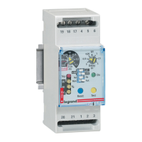
Identifies specific LEXIC product series like 260 92/93/94/95 and 260 96/97/98.

Device Component Descriptions

Details each functional part of the relay, including controls, indicators, and settings.

Adjustment of IΔn

Setting the residual current threshold (IΔn) for tripping.

Test Button Functionality

Button used to perform a functional test of the relay's operation.

Reset Button Operation

Button to reset the relay after it has tripped or encountered a fault.

Voltage Presence Indicator

Green LED that confirms the presence of a power supply to the device.

Tripping and Interruption Indicators

Red LED indicates relay trip or flashing red for connection interruption.

Time Delay Setting

Allows adjustment of the tripping delay time for the relay.

IΔn Rating Selection

Selector for choosing the appropriate residual current sensitivity rating.

Reset Mode Selection

Choice between manual or automatic reset operation for the relay.

Output Relay Status Setting

Configuration for the operational state of the output relay contacts.

Fault Current Percentage Display

Indicates the detected fault current as a percentage of the set IΔn.

Positive Safety Contact Behavior

Contact Operation (Terminals 18-17)

Details contact closure between terminals 18 and 17 under power or fault conditions.

Contact Operation (Terminals 18-19)

Details contact closure between terminals 18 and 19 under power or fault conditions.

Standard Safety Contact Behavior

Contact Operation (Terminals 18-17)

Describes contact closure between terminals 18 and 17 during normal powered states.

Contact Operation (Terminals 18-19)

Describes contact closure between terminals 18 and 19 during normal powered states.

Relay Settings and Adjustments

Current Threshold (IΔn) Adjustment

Visual guide and table for setting the residual current trip threshold.

Time Delay (t=0) Adjustment

Visual guide for adjusting the time delay setting for the relay.

Model Current Ratings

Table listing internal diameter and minimum current for various relay models.

Wiring and Installation Precautions

Guidelines for minimizing distances, using proper cables, and avoiding interference.

Reset Mode Programming

Manual Reset Mode

Alarm status persists until manually reset by the operator.

Automatic Reset Mode

Device attempts automatic resets up to three times after an alarm.

Reset Limitation

Note: Automatic reset is impossible for fault currents at 50% or higher of programmed IΔn.

Related product manuals