0,3...3A0,03...0,3A 3...30A
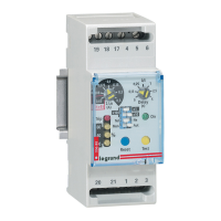
DESCRIZIONE FRONTALE FRONT DESCRIPTION
∂Predisposizione I
Δ
n soglia d’intervento
À Selettore portata x1 / x10 / x100
Controllare che il valore d’intervento selezionato sia compatibile con le sensi-
bilità minima rilevabile dal trasformatore toroidale abbinato.
à • Õ LED segnalazione
LED spento
LED acceso
LED lampeggiante
ΠPulsante di prova
Permette di simulare la condizione di allarme, l’accensione del LED Trip e la
commutazione del relè d’uscita.
œ Pulsante di ripristino lo stato di allarme permane fino a quando l’operatore
non agisce sul tasto RESET.
Il ripristino è inibito con corrente differenziale persistente:
> 50% I
Δ
n impo-
stata
– Selettore PF / AL.50%
PF
= allarme (17-18-19) + segnalazione mancanza rete POWER FAIL (60-61-62)
Al.50% = allarme (17-18-19) + preallarme 50% I
Δ
n (60-61-62)
— Selettore stato relé uscita: Nd (
norm. diseccitato)
sicurezza negativa -
Ne
(
norm. eccitato)
sicurezza positiva.
Il relè di preallarme è sempre norm. diseccitato
Il relè POWER FAIL è sempre norm. eccitato
.
“ Predisposizione ritardo intervento
Selezionando la soglia d’intervento nella posizione 0,03 viene automaticamen-
te escluso il ritardo intervento, indipendente dalla posizione del selettore di
portata À
Per predisporre soglia di intervento ∂ I
Δ
n = 30mA con intervento istantaneo
sele zionare 0,03 e accertasi che il selettore À sia in posizione x1.
” Indicazione istantanea della corrente differenziale (in % del valore I
Δ
n impostato)
Inserzione (on) - esclusione (off) filtro per componenti armoniche.
ATTENZIONE
Inserendo il filtro per componenti armoniche, il differenziale non deve essere
utilizzato per la protezione delle persone.
ISTRUZIONI DI CABLAGGIO
• La posizione di fissaggio risulta completamente indifferente ai fini del funzio-
namento.
• Le operazioni di predisposizione (soglia intervento, tempo ritardo, ecc.)
devono essere effettuate con apparecchio non alimentato.
• Rispettare scrupolosamente lo schema d'inserzione, una inesattezza nei collegamenti è
ineviitabilmente causa di funzionamento anomalo o di danni all'apparecchio.
• L'ottenimento della piena funzionalità del sistema di protezione differenziale è legato
alle modalità di installazione, per cui si consiglia:
+Ridurre al minimo la distanza tra toroide e relè
+Utilizzare cavi schermati o intrecciati per la loro connessione
+Evitare di disporre i cavetti di connessione toroide-relè parallelamente a
conduttori di potenza
+Evitare di installare toroide e relè in prossimità di sorgenti di campi elettroma-
gneti ci intensi
(grossi trasformatori).
+Solo i conduttori attivi attraversano il toroide (dis.D1)
+Utilizzando cavo schermato, l’armatura deve essere collegata a terra come da
(dis.D2)
+I conduttori devono essere posizionati al centro del toroide (dis.D3). n
∂ Setting intervention threshold I
Δ
n
À Range selector x1 / x10 / x100
Check that selected intervention value matches the lowest sensibility detec-
table by the connected ring current transformer.
à •
Õ S
ignaling LED
LED off
LED on
LED blinking
ΠTest key
It allows to simulate alarm condition, LED Trip switching on and output
relay switching.
œ Reset key the alarm stays until the operator doesn’t act on RESET key.
Reset is not possible with persistent residual current:
> 50% I
Δ
n.
– Selector PF / AL.50%
PF = alarm
(17-18-19) + POWER FAIL signaling (60-61-62)
Al.50% = alarm
(17-18-19)
+ pre-alarm 50%
Δ
n
(60-61-62)
— Switch for state of output relay: Nd (normally de-energised) negative security
Ne
(normally energised) positive security.
Pre-alarm relay is always normally de-energized
.
POWER FAIL relay is always normally energised
“ Setting intervention delay
Selecting the intervenction threshold on position 0,03 the intervention delay
is automaticall excluded, independently of position of range selector, À.
To set intervention threshold ∂ I
Δ
n = 30mA with instantaneous interven-
tion, select 0,03 and make sure that selector À is on position x1.
” Instantaneous display of earth leakage current (in % of selected I
Δ
n value)
On-off harmonic filter
ATTENTION
By connecting the harmonic component filter, the differential must not be used
to protect people.
WIRING INSTRUCTIONS
• Mounting position do not affect in any way the proper working.
• Setting operations (intervention threshold, delay time, etc.) must be carried
out with non-fed meter.
• Please carefully follow the wiring diagram; an error in connecting the relay
may give rise to irregular working or damages.
• Four full functional of the earth relay the following installation recommen-
dation should be adopted.
+To reduce as much as possible the distance between ring current transformer
and relay.
+To use only shielded or twisted cables for their connection
+To avoid in placing ring current transformer-relay connection cables
parallelly to power wires
+To avoid in mounting ring current transformer and relay near sources of intense
electromagnetic fields
(big transformers).
+Pass active conductor only through toroid (draw D1)
+When using blind cable, ensure ground connection of armature (draw D2)
+Ensure the central positioning of conductor through toroid (draw D3). n
0
,03
0
,05
0
,075
0
,1
0
,15
0
,2
0
,3
x1 30mA 50mA 75mA 100mA 150mA 200mA 300mA
x
10
3
00mA
5
00mA
7
50mA
1
A
1
,5A
2
A
3
A
x
100
3
A
5
A
7
,5A
1
0A
1
5A
2
0A
3
0A
I
Δ
n
Ã
On
Õ
Trip / Fail
• •
Assenza tensione alimentazione ausiliaria o apparecchio fuori servizio
Lack of auxiliary voltage supply or out of order meter
Z
•
Sorveglianza • Supervision
Z Z
A
llarme • Alarm
Z • Z • Z
I
nterruzione collegamento toroide - relè
Connection breakdown between relay and ring current transformer
•
Z
•Z•Z
~
0n
PF
0ff
h.f.filter
55
66
88
3
3
1111
99
10
22
1
44
7
7
Istruzioni d’uso
User’s Guide
RD3B2
BTicino SpA
Viale Borri, 231
21100 Varese - ITALY
www.imeitaly.com
LE12568AA 10/20 - 01 IM