L1
L2
L3
N
20
B A
AUX.SUPPLY
Bm
TD
6
4
(+)
(-)
TRANSFORMER
RESET
TEST
1
3
2
21 19 18 17
60 61 62
50%
TRIP
L1
L2
L3
N
20
B A
AUX.SUPPLY
Ba
TD
6
4
(+)
(-)
TRANSFORMER
RESET
TEST
1
3
2
21 19 18 17
60 61 62
50%
TRIP
L1
L2
L3
N
20
B A
AUX.SUPPLY
Bm
TD
6
4
(+)
(-)
TRANSFORMER
RESET
TEST
1
3
2
21 19 18 17
60 61 62
50%
TRIP
L1
L2
L3
N
20
B A
AUX.SUPPLY
Ba
TD
6
4
(+)
(-)
TRANSFORMER
RESET
TEST
1
3
2
21 19 18 17
60 61 62
50%
TRIP
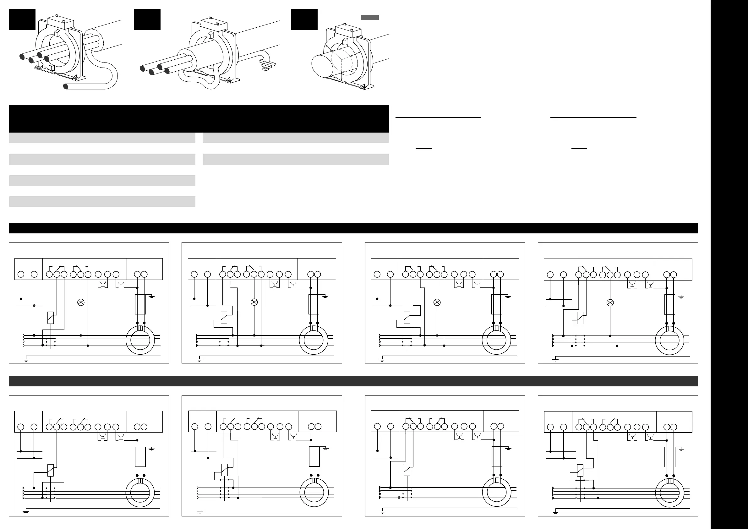
S 291/100
S 291/101 S 291/102 S 291/99
SICUREZZA NEGATIVA • NEGATIVE SECURITY PF SICUREZZA POSITIVA • POSITIVE SECURITY
L1
L2
L3
N
20
B A
AUX.SUPPLY
Bm
TD
6
4
(+)
(-)
TRANSFORMER
RESET
TEST
1
3
2
21 19 18 17
60 61 62
TRIP POWER FAIL
L1
L2
L3
N
20
B A
AUX.SUPPLY
Bm
TD
6
4
(+)
(-)
TRANSFORMER
RESET
TEST
1
3
2
21 19 18 17
60 61 62
TRIP POWER FAIL
L1
L2
L3
N
20
B A
AUX.SUPPLY
Ba
TD
6
4
(+)
(-)
TRANSFORMER
RESET
TEST
1
3
2
21 19 18 17
60 61 62
TRIP POWER FAIL
L1
L2
L3
N
20
B A
AUX.SUPPLY
Ba
TD
6
4
(+)
(-)
TRANSFORMER
RESET
TEST
1
3
2
21 19 18 17
60 61 62
TRIP POWER FAIL
S 291/140
S 291/141S 291/142S 291/143
SICUREZZA NEGATIVA • NEGATIVE SECURITY Al.50% SICUREZZA POSITIVA • POSITIVE SECURITY
D1 D2 D3
NUCLEO CHIUSO / CLOSED CORE
CODICE PASSAGGIO CAVO IΔn min
(1)
In 6In
CODE PASSING CABLE A A A
TDGA2 Ø 28 0,03 65 390
TDGB2 Ø 35 0,03 70 420
TDGH2 Ø 60 0,03 90 540
TDGC2 Ø 80 0,05 170 1020
TDGD2 Ø 110 0,1 250 1500
TDGE2 Ø 140 0,3 250 1500
TDGF2 Ø 210 0,3 400 2400
NUCLEO APRIBILE / OPEN CORE
CODICE PASSAGGIO CAVO IΔn min
(1)
In 6In
CODE PASSING CABLE A A A
TDAA2 Ø 110 0,5 250 1500
TDAB2 Ø 150 0,5 250 1500
TDAC2 Ø 300 1 630 3780
D
iametro: diametro foro interno trasformatore (passaggio cavi/sbarre)
I
Δn min: valore minimo di I n impostabile sul relè differenziale abbinato al
t
oroide
I
n: corrente nominale dell’interruttore o sezionatore
I valori indicati sono validi unicamente con i conduttori passanti esatta-
mente al centro del toroide
Es. Scelta trasformatore toroidale per corrente nominale interruttore
(
In) = 125A
Rispettando i parametri indicati dalla normativa
IEC/EN 60947-2 allegato M.
o
ccorre utilizzare un trasformatore
T
DGC2
C
orrente In = 170A
C
orrente 6In = 1020A
In impianti con correnti transitorie deboli (< a 6In) è possibile utilizzare
t
rasformatori toroidali di dimensioni inferiori, attenendosi alla seguente
f
ormula:
6In
(valore indicato in tabella)
=
max. sovraccarico ammesso
I
s
(
corrente nominale dell’interruttore utilizzato)
Es. Utilizzando un trasformatore TDGH2 con valore
6In = 540A
con inter-
r
uttore con corrente nominale In=125A
5
40A
= 4,32
125A
Il massimo sovraccarico ammesso è pari a 4,32 volte la corrente dell’inter-
r
uttore
D
iameter: internal hole of the transformer (bus bar and cable passage)
I
Δn min: minimum value to be set on the Earth Leakage Relay in order to
a
void unwanted tripping
I
n: rated current of the switch
The specified values are valid if the cables are positioned in the centre of
the transformer
E.g. How to choose the correct transformer for a specific nominal current
(
In) = 125 A
To comply with the specification of the standard
IEC/EN 60947-2 annex M
,
t
he type
T
DGC2
s
hould be used
C
urrent In = 170A
C
urrent 6In = 1020A
Where the transients current are not so high, smaller transformers
(
< a 6In) may be used provided that the following calculation is respected:
6
In (see table)
= max overload permissible
I
s (nominal current of the switch)
E
.g. A
T
DGH2
t
ype with value
6
In = 540A
i
n conjunction with a switch of
In=125A
5
40A
= 4,32
125A
Permissible maximum overload is
4,32
times the In of the switch.
 Loading...