This document outlines the installation and features of the Legrand Galaxy system, which includes servers, stations, and accessories designed for robust network connectivity.
Servers
The Galaxy system offers two main server types: a Large server (Cat. No: 659182) and a Medium/Small server (Cat. No: 659181 / 659180). Both server types are designed for reliable operation within a network infrastructure.
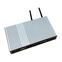
Large Server (Cat. No: 659182)
Function Description: The Large server acts as a central hub for the Galaxy system, managing network operations and data. It is equipped with multiple LAN ports for extensive connectivity.
Components:
- Server unit (x 1)
- Antenna (x 2)
- Mains power supply adapter and cable - Black (x 1)
- Connectors - Green (x 3)
- Mounting bracket (x 2)
- Mounting screws (x 4 pcs)
Usage Features:
- Power button LED indicator:
- Amber: Indicates standby power.
- Blue: Indicates power is ON.
- OFF: Indicates power is OFF.
- HDD LED: Flashes during hard drive activity, indicating data access or processing.
- PWR LED indicator:
- Green: Indicates power is ON.
- OFF: Indicates power is OFF.
- Connectivity: Features 4 LAN Ports for network connections.
Medium Server (Cat. No: 659181) / Small Server (Cat. No: 659180)
Function Description: These servers provide similar functionality to the Large server but are designed for smaller scale deployments, offering a more compact solution.
Components:
- Server unit (x 1)
- Antenna (x 2)
- Mains power supply adapter and cable - Black (x 1)
- Mounting screws (x 4 pcs)
Usage Features:
- Power button LED indicator:
- Blue: Indicates power is ON.
- OFF: Indicates power is OFF.
- Connectivity: Features 2 LAN Ports (specifically for the Small server, implying the Medium server may have more or the same).
Stations
The Galaxy system includes various station types: Small, Medium, and Large, each designed for specific deployment scenarios and offering different levels of connectivity and range.
Small Station (Cat. No: 659183)
Function Description: The Small Station is a compact unit designed for network communication, featuring LED indicators for power, communication status, and traffic.
Components:
- Station unit (x 1)
- Antenna (x 1)
- Mains power supply cable (x 1)
- Wall Mounting bracket with screws (x 1)
Usage Features:
- LED 1 - Power:
- Red (Blinking): During system initialisation.
- Green (Blinking): During system initialisation.
- Green: When initialisation is complete.
- LED 2 - Communication:
- Red: During system initialisation / Communication disconnected.
- Green (Blinking): During communication initialisation.
- Green: Communication established.
- LED 3 - Communication traffic:
- Red: During initialisation.
- Green (Blinking): Indicated data is being received.
- Red (Blinking): Indicated data is being sent.
Large Station (Cat. No: 659185) / Medium Station (Cat. No: 659184)
Function Description: These stations are designed for broader coverage and more robust network communication, suitable for larger installations. They include specific components for earthing and mounting.
Components:
- Station unit (x 1)
- Earthing wire and glands (x 1)
- Large Antenna (x 1 Large Station only)
- Antenna cable (x 1 Large Station only)
- Antenna Adapter (x 1 Large Station only)
- POE injector with power cable (x 1)
- Wall Mounting bracket with screws (x 1)
Usage Features:
- LED Indications:
- Green: Power ON.
- Red (Blinking): During system initialisation.
- OFF: When initialisation is complete.
Mounting Brackets
The system provides specific mounting brackets for each station type to ensure secure and optimal placement.
- Large station mounting: Supports mounting with or without an adapter, allowing flexibility in antenna placement.
- Medium station mounting: Designed for wall mounting.
- Small station mounting: Also designed for wall mounting.
Things to Consider Before/After Installation
Maintenance Features:
- Safety: Isolate 240 V mains supply before maintenance or installation.
- Power Cycling: None of the devices should be switched On/OFF after installation.
- LED Indicators: Follow the LED indicator functions for troubleshooting and status checks.
- Antenna Placement (Large station only):
- Ensure the antenna is pointing vertically upwards.
- Place the antenna away from walls and surfaces for effective performance.
- Mounting: The mounting bracket must be installed to achieve optimum performance. Secure the stations onto the mounting bracket on the desired wall or structure before connecting.
Earthing Galaxy Stations and Accessories
Proper earthing is crucial for the safety and longevity of the Galaxy system.
Earthing the Medium and Large Stations
Maintenance Features:
- The station is provided with a green/yellow cable for earthing.
- A pre-existing screw hole with an earth symbol is available on the metal enclosure for connection.
Earthing the Station Mounting Bracket
Maintenance Features:
- It is strongly recommended to earth the station mounting bracket to prevent surges that may damage the station.
- Pole mounting: Earthing can be completed by using metallic strapping.
- Wall mounting: Use M4 screws (provided). The earthing connection is done through a ring terminal. A specific crimping tool is required to perform the operation, as the ear earthing cable must be crimped inside this ring terminal.
Ethernet Connection
The Galaxy system supports both direct and extended Ethernet connections.
Usage Features:
- Power-up Sequence:
- Plug the power cord of all units into the power outlet (Do not turn ON initially).
- Connect the Server, POE, and Station to an available Ethernet socket outlet. Ensure all devices are on the same subnet (local IT assistance may be needed).
- Turn ON the power at the outlet; the Server will automatically turn ON.
- Maximum Distance: The maximum distance between the POE injector and the station should be less than 100 m.
- Direct Connection:
- Use a Legrand yellow Cat 6 cable (Cat. No. 659187) for direct connection from the Server to the Station.
- For multiple stations, they are wired back to the Server in a star formation.
- If the distance between the Server and Station exceeds 100 m, a Galaxy LAN extender accessory (Cat. No: 659187) must be used.
- Commissioning: Contact Legrand prior to installation and for commissioning.
Galaxy Accessories
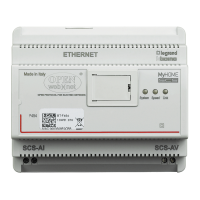
Ethernet Extender Kit (Cat. No: 659188)
Function Description: This kit extends the reach of Ethernet connections, allowing for greater distances between network components.
Technical Specifications:
- Connection: Uses Cat 6 cable (Cat. No 659187) for extension.
- Distance: Effective for distances greater than 1.8 m.
Usage Features:
- LED indication:
- ON: Power good.
- ON: Link established.
- FLASH: Activity (The green LED may blink quickly while connecting, especially for long runs, taking a few seconds to optimise the link).
- POE Status (Green):
- In normal operation, the LEDs display the power available in flashing or steady green.
- Power levels (in watts): 5, 10, 15, 20, 25.
- ON: POE enabled to station.
- FLASH: POE not enabled, no compliant device detected.
- The power level is displayed after the station-side unit powers up. Available power depends on the cable length, cable gauge, and the POE source used.
Warranty and Customer Service
Maintenance Features:
- Warranty: Legrand Australia Pty Ltd offers a 5-year warranty from the date of purchase. This warranty covers major failures and provides for replacement or refund, as well as repair for goods that fail to be of acceptable quality but do not amount to a major failure, in accordance with Australian and New Zealand Consumer Laws.
- Customer Service: For customer service and technical support inquiries, contact Legrand Australia at 1300 369 777 or Legrand New Zealand at 0800 476 009, Monday to Friday during business hours.
- Websites: www.legrand.com.au and www.legrand.co.nz.
- ABN: 31 000 102 661.