Do you have a question about the LEGRAND On-Q and is the answer not in the manual?
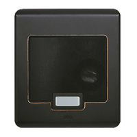
Details the 2-gang intercom video door unit and its available finishes for mounting.
Guide for installing the Video Door Unit during new construction, before drywall.
Instructions for wiring and final mounting after drywall installation.
Explains how the door chime button alerts occupants and enables two-way communication.
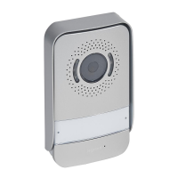
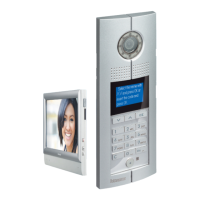
The On-Q/Legrand Selective Call Intercom Video Door Unit, identified by PN IC5003-XX, is a weather-resistant outdoor device designed to enhance home security and communication. Its primary function is to allow visitors to notify occupants of their presence and facilitate two-way communication. The unit integrates seamlessly with an optional On-Q LCD Console and associated module, providing a comprehensive intercom system.
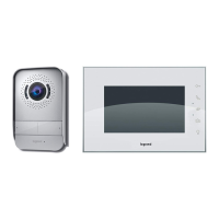
When a visitor presses the door chime button on the Video Door Unit, one of 20 selectable door chimes will sound throughout the home at each active intercom unit. This alerts occupants to the visitor's presence. Occupants can then use any Room Unit or enabled Patio Unit to initiate two-way communication with the visitor. The visitor will hear the occupant's voice through the Video Door Unit's speaker and can respond using its microphone. This allows for clear and convenient communication without needing to open the door.
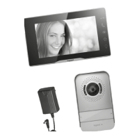
A key feature of the system is the ability for occupants to see who is at the door via the optional On-Q LCD Console. This visual verification adds an extra layer of security, allowing occupants to identify visitors before engaging in conversation or granting access. For added convenience and security, the system also supports an optional door release function. If a separate door release device is installed, occupants can remotely open the door for the visitor directly from their intercom unit.
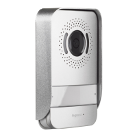
The Video Door Unit is a 2-gang product, designed for mounting within a standard two-gang electrical box. For unique or retrofit installations, a two-gang surface-mount box (P/N IC5006-BK) is also available. The recommended mounting height for the electrical box is 56 inches from the floor to the bottom of the box. The unit is available in a variety of finishes to complement different architectural styles, including white (-WH), shiny brass (-SB), antique brass (-AB), brushed stainless (-BS), and oil-rubbed bronze (-OB).
Installation of the Selective Call Video Door Unit is typically performed in two main stages during new construction: "Rough-in" and "Trim-out." During the "Rough-in" phase, before drywall and siding are installed, a Cat 5 cable is run from the enclosure where the Selective Call Intercom Module will be located to the 2-gang box at the Video Door Unit location. It's crucial to note that a single Video Door Unit in a one-module system can be up to 650 feet from the module, making it suitable for gate applications. However, all other Door Units on the system must be within 330 feet (100 meters) of the Distribution Module. To prevent interference, all Category 5e cable runs should be kept at least 12 inches away from AC electrical cables. If crossing an AC cable is unavoidable, it should be done at a 90-degree angle.
The "Trim-out" phase occurs after drywall installation. This involves terminating the Cat 5 cable with an RJ45 plug, following the T568A pin assignments. Accurate termination using T568A standards is essential for all locations within the Selective Call Intercom System. The RJ45 plug is then inserted into the RJ45 jack on the rear of the Video Door Unit. Before mounting the unit, a weather-proofing gasket must be placed against the gang or back box and secured with the included mounting bracket. The mounting bracket should be installed with its center tab pointing upwards, as the Video Door Unit will be "hung" from this tab. Slotted holes in the bracket allow for leveling the unit if the gang or back box was installed off-level.
After the mounting bracket is secured, the Cat 5 cable is pulled through it, and the RJ45 plug is inserted into the jack on the rear of the Video Door Unit. The unit is then hung from the top tab of the mounting bracket, and two set screws at the bottom are tightened with a 1/16" allen wrench to secure it in place. The other end of the Cat 5 cable is terminated at the Selective Call Intercom Module with an RJ45 plug, also using the T568A wiring standard, and inserted into jack #8 (labeled 8/V1) on the SCI Intercom Module.
The Video Door Unit features a four-position terminal block on its rear, which serves two purposes. The CHIME output provides a normally open dry contact closure, used to ring a customer's third-party door chime when the Video Door Unit button is pressed. The SENSOR input is reserved for future applications.
Once all units and modules are connected, power is applied to the Selective Call Intercom Module. The system will then automatically discover and display all Selective Call Room, Door, and Patio Units on each Room Unit LCD, verifying system functionality. For detailed instructions on configuring and personalizing the Selective Call System, users should refer to the Selective Call System Installation Manual (P/N 1308003) and the Selective Call System User Manual (P/N 1308001). Information regarding support for electronic door release functionality can be found in the Selective Intercom 8 Location Distribution Module Information Sheet (IS-0385).
The Video Door Unit incorporates a camera, microphone, and speaker to facilitate its communication functions. The camera provides visual feedback to occupants, the microphone captures the visitor's voice, and the speaker allows occupants to communicate with the visitor. The door chime button is the primary interface for visitors to announce their presence. The robust design and weather-resistant features ensure reliable operation in outdoor environments.
| Brand | LEGRAND |
|---|---|
| Model | On-Q |
| Category | Intercom System |
| Material | Plastic |
| Color | White |