2
LVS-1
Load
Rear Housing
Depluggable
Te
rminal
Front Cover
Ceiling
Spring Clips (2)
Blue
Control Out
Black
+24V
Low Voltage
Class 2
Line Voltage
Line
Neutral
Feed Through
Power Pack
Man.Switch
Red
Common
For low voltage
momentary switch, set
DIP switch #6 ON
Man.Switch
+24V
Jumper
Back
of
LVS-1
Load #1
Load #2
(Optional)
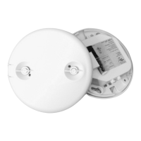
UT-305
Rear Housing
Depluggable
Te
rminal
Front Cover
Ceiling
Spring Clips (2)
Blue
Control Out
+24V
Common
Low Voltage
Class 2
Line
Voltage
Line
Neutral
Feed Through
Power Pack
Black
Red
#1 #2
Line Voltage
Switches
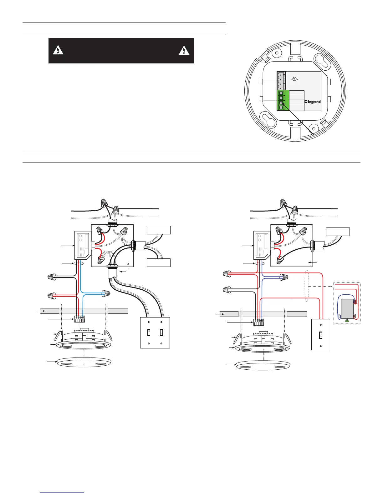
WIRING DIRECTIONS
Each Wattstopper BZ series power pack can supply power for 5 UT-305 sensors.
When using more sensors than this, multiple power packs are required.
Refer to the wiring diagram for the following procedures:
Connect the low voltage:
• RED wire (+24VDC) from power pack to the +24V terminal on the sensor.
• BLACK wire (Return) from power pack to Common terminal on the sensor.
• BLUE wire from power pack to Control Out terminal on sensor.
To add a manual switch such as the LVS-1 Momentary Toggle Switch, or RS2-3
Low Voltage Momentary Switch to the above applications–connect:
• Wire from one side of switch to +24V terminal on sensor.
• Wire from other side of switch to Man Switch terminal on sensor.
WARNING: TURN THE POWER OFF AT THE
CIRCUIT BREAKER BEFORE WIRING.
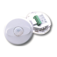
UT-305
Ultrasonic
Occupancy Sensor
U.S.Patents:
5,640,113
Patent Pending
40kHz Ultrasonic
+24VDC/VAC
Connect to Watt Stopper
Class 2 Power Packs
For Indoor Use Only
03624r2
Control Out.
Man. Switch
+24V
Common
LISTED
88T9
Appliance
Control
v3
Wiring
terminals
CONNECTING WIRES
• Care should be taken to separate high voltage power from low voltage (Class 2) control wiring.
• All connections to sensor are low voltage, Class 2.
Standard wiring with local off switch Manual-On wiring with low voltage momentary switch
 Loading...