Wattstopper
®
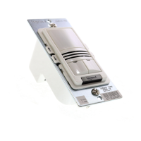
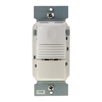
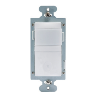
DLM Dual Technology Wall Switch Occupancy Sensor
Interrupteur mural avec détecteur de présence à technologie DLM double
Sensor e interruptor DLM con tecnología dual
Quick Start Guide • Guide de démarrage rapide • Guía de inicio rápido
No: 23121 – 07/16 rev. 2
Catalog Numbers • Les Numéros de Catalogue • Los Números de Catálogo: LMDW-101, LMDW-102
Country of Origin: Made in China • Pays d’origine: Fabriqué en Chine • País de origen: Hecho en China
Models ending in -U are BAA and TAA compliant (Product produced in the U.S.)
SPECIFICATIONS
Voltage .............................................................................. 24VDC
Current Consumption ...........................................................20mA
Power Supply ................................. Wattstopper Room Controller
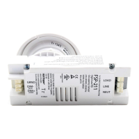
Connection to the DLM Local Network .................... 2 RJ-45 ports
DLM Local Network Characteristics when using LMRC-11x/2xx
room controllers:
Provides low voltage power over Cat 5e cable (LMRJ).
Supports up to 24 communicating devices, including 4
LMRC-10x or LMPL-101 max per each DLM Local Network.
Free topology up to 1,000ft of low voltage cable.
Environment ................................................. For Indoor Use Only
Operating Temperature .................32° to 131°F (0° to 55°C)
Storage Temperature ...................23° to 176°F (-5° to 80°C)
Relative Humidity .......................5 to 95% (non condensing)
Patent Pending
This unit is pre-set for Plug n’ Go™ operation, adjustment is optional.
For full operational details, adjustment and more features of the product, see the DLM System Installation Guide provided with Wattstopper room
controllers, and also available at www.legrand.us/wattstopper.
Installation shall be in accordance with all applicable regulations, local and NEC codes. Wire connections shall be rated suitable for the wire size
(lead and building wiring) employed.
For Class 2 DLM devices and device wiring: To be connected to a Class 2 power source only. Do not reclassify and install as Class 1, or Power and
Lighting Wiring.
Do not apply cleaning solvent directly onto unit. Apply cleaning solvent onto a cloth, then wipe the unit to clean it..
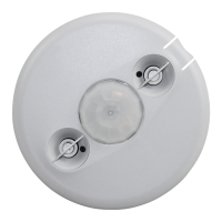
COVERAGE PATTERN
Do not obstruct the lens.
NOTE: Plus 10° above horizon.
40 ft
40 ft
25 ft
25 ft
TOP
180°
Major motion
Minor motion
Major motion
Minor motion
PIR
Coverage
Ultrasonic
Coverage
4 ft
SIDE
VIEW
25 ft
5 ft
(9.1m)
20’
(6.1m)
35 ft
35 ft
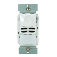
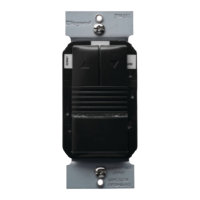
BUTTONS AND INDICATORS
Up
Down
Select
Configure
PIR Lens
Lens release
Button LED
IR Window
LMDW-101
PIR Detection LED
Ultrasonic Detection LED/
Sensor Binding LED
Button
On/Off
MOUNTING
WARNING: Do Not Install To Cover
a Junction Box Having Class 1, 3 or
Power and Lighting Circuits.