Wattstopper
®
High/Low/Off PIR Fixture Integrated Outdoor Sensor
Haut/Bas/Éteint Luminaire avec détecteur IRP extérieur intégré
Alto/Bajo/Apagado Sensor PIR para fixturas y uso exterior
Installation Instructions • Instructions d’Installation • Instrucciones de Instalación
No: 24057 – 12/17 rev. 3
Catalog Number • Numéro de Catalogue • Número de Catálogo: FSP-211
Country of Origin: Made in China • Pays d’origine: Fabriqué en Chine • País de origen: Hecho en China
FSP-211-U is BAA and TAA compliant (Product produced in the U.S.)
DESCRIPTION AND OPERATION
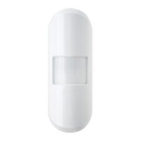
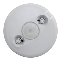
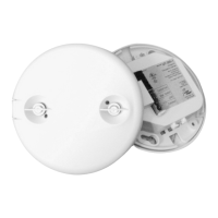
The FSP-211 is a motion sensor that dims lighting from high to low
based on movement. This slim, low-profile sensor is designed for
installation inside the bottom of a light fixture body. The PIR lens
module connects to the FSP-211 through a 1.30" diameter hole in
the bottom of the fixture.
The sensors use passive infrared (PIR) sensing technology that
reacts to changes in infrared energy (moving body heat) within the
coverage area. Once the sensor stops detecting movement and
the time delay elapses lights will go from high to low mode and
eventually to an OFF position if it is desired. Sensors must directly
“see” motion of a person or moving object to detect them, so
careful consideration must be given to sensor luminaire placement
and lens selection. Avoid placing the sensor where obstructions
may block the sensor’s line of sight.
The FSP-211 operates at 120V/277V, and 230V-240V Single
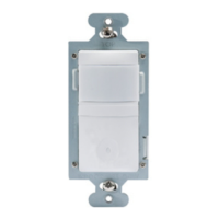
Phase. No power pack is required. It is designed to be installed in
both indoor and outdoor environments.
SPECIFICATIONS
Voltage ..................... 230-240V, 50/60Hz, Single Phase: TUV, CE
...................................120V/277V, 50/60Hz: UL/cUL Listed
Load Ratings
@ 230-240V ......................... 0-300W Ballast or LED Driver
@ 120V ............. 0-800W Tungsten, Ballasts or LED Driver
Motor @ 120V/277V ................................................ 1/6 HP
@ 277V ..............................0-1200W Ballast or LED Driver
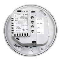
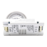
Wiring Terminals
Line Voltage ..........................................Line, Neutral, Load
..................................................................14AWG-18AWG
Low Voltage .................Dim + (violet), Dim - (gray), Ground
..................................................................18AWG-20AWG
Use Solid or Tinned Stranded Copper Conductor
Operating Temperature ....................-40°F (-40°C) to 167°F (75°C)
Tightening Nut Torque .................................................. 25-30 in-lbs
Dimensions
Collar ........................................... 1.30” diameter (33.0mm)
Collar height ................................................0.64” (16.3mm)
Body ......1.38” x 3.8” x 0.9” (35.1mm x 96.5mm x 22.9mm)
Weight ........................................................................2.8 oz (80 g)
Coverage
FSP-L2 Lens @ 8’ height ....................... up to 44’ diameter
FSP-L3 Lens @ 20’ height ..................... up to 40’ diameter
FSP-L7 Lens @ 40’ height ................... up to 100’ diameter
Adjustments and Features
High Mode ............................................................ 0 V -10 V
Low Mode ............................................. . . . 0 V - 9.8 V, Off
Time Delay ...............................30 seconds, 1 min - 30 min
Cut Off ...........................Disable, 1 min - 59 min ,1 hr - 5 hr
Sensitivity .......................... On-Fix, Off-Fix, Low, Med, Max
Hold Off Setpoint .......................... Auto, None, 1 fc - 250 fc
Ramp Up .........................................Disable, 1 sec - 60 sec
Fade Down ...................................... Disable, 1 sec - 60 sec
Photocell Setpoint for On/Off ................................. 1-250 fc
Factory Defaults
High Mode .................................................................... 10 V
Low Mode .............................................................. . . . 1 V
Time Delay ................................................................. 5 min
Cut Off ........................................................................... 1 hr
Sensitivity .................................................................... Max
Hold Off Setpoint .................................................... Disable
Ramp Up ................................................................. Disable
Fade Down .............................................................. Disable
Photocell Setpoint for On/Off .................................. Disable
OPEN DEVICE for installation in the Listed Enclosure per
Installation Instructions.
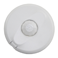
IR Receiver
IR Transmitter
Light Sensor
Motion Indicator
Red LED
PIR Sensor
Sensor Protection Cap
NOTE: Remove Cap before use
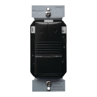
Once powering the device up, the FSP-211 will use factory default
parameters to operate. If adjustments are needed, Wattstopper
FSIR-100 configuration tool must be used.
Occupancy Sensor
5E4
15195r1
LOAD
LINE
NEUT
(violet)
(grey)
Class 2 Wiring Only
18-20 AWG Solid CU Wire Only
230 VAC, 50 Hz
1200W max ballast
FSP-211
GRND
DIM-
DIM+
14-18 AWG Soli
d CU Wire Only
High/Low PIR