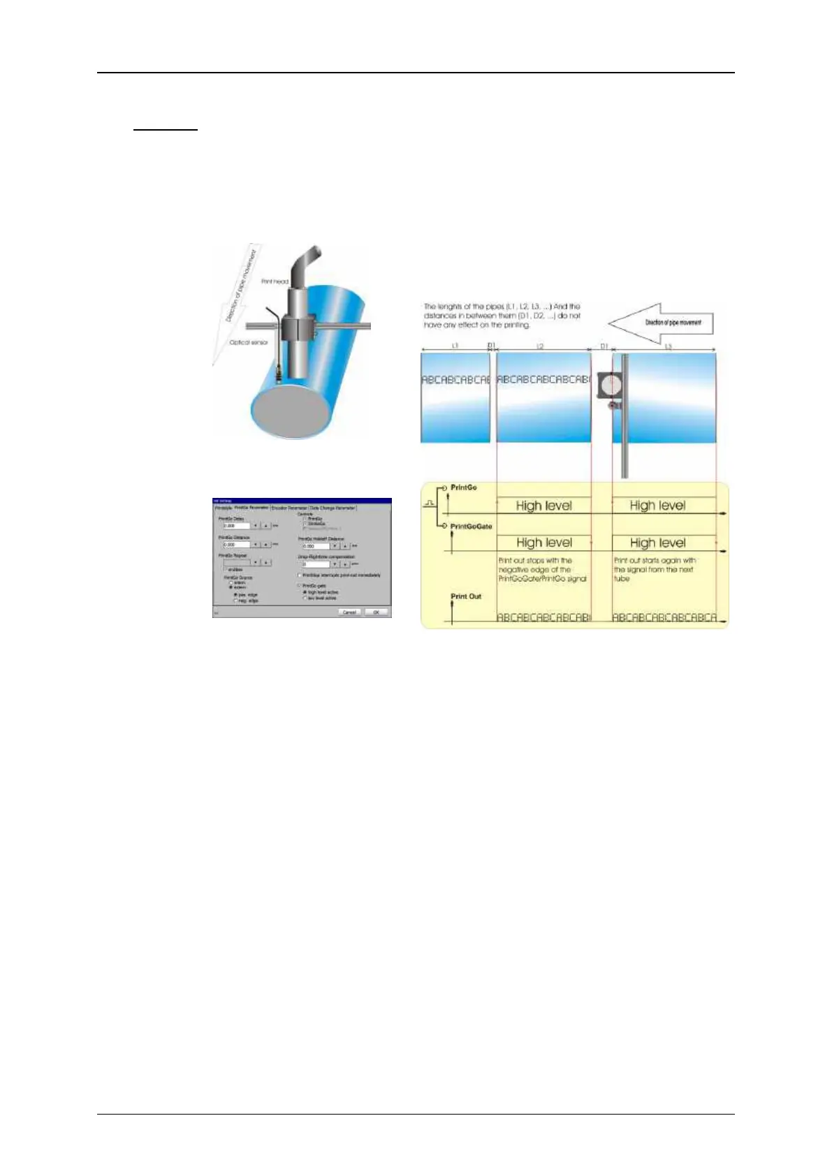
In this example the print shall be carried out on tubes. The printout is an
endless print (e.g. Type, date of manufacturing, material etc.) and not
each tube has the same length. In addition the distances between the
tubes are not always the same. The basic mounting of the sensor and the
print head is shown in Picture 13.
As shown in Picture 13 the print head and the sensor should be installed
in parallel to each other. If the sensor and the print head would be installed
in row the stopping of the printout at the end of a tube would be either
too early or too late.
The printout shall start with the beginning of each tube and it shall stop
at the end of it without printing in the space between the tubes. For this
a sensor which recognizes the beginning and the end of a tube is used.
The output of the sensor is connected to the PrintGo and the PrintGoGate
input of the JET printer (see Picture 15). With this design the PrintGo
signal together with the PrintGoGate signal starts the printout and with
the negative edge received from the sensor at the end of the tube the
printout stops.
The signal from the sensor is used for the PrintGo input as well as for the
PrintGoGate input. For the PrintGoGate input you need a high level and
not only a positive edge as for the PrintGo input. Therefore it is important
that the signal from the Sensor is a signal level and not only a signal edge.