•
Rotation around the X-axis – Omega w
•
Rotation around the Y-axis – Phi j
•
Rotation around the Z-axis – Kappa k
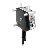
The reflectors are at the centre of each face of the T‑Scan. The reflectors are
glass prisms which reflect the AIFM laser beam of the Laser Tracker to sup-
port the initial distance measurement of the Absolute Distance Meter (ADM)
and the tracking measurement of the Interferometer (IFM). These measure-
ments provide the 3D information.
There are several marker LEDs on each face of the T‑Scan which have a three-
dimensional distribution. These LEDs operate infrared.
Each marker LED has a unique ID, which identifies the LED and its position on
the device.
The marker LEDs are flashing in accordance with the synchronisation fre-
quency. The Absolute Tracker controller provides a real-time feedback loop to
monitor the illumination and the identification of the marker LEDs.
The real-time control optimises the illumination of the marker LEDs for the
measurement. It also reduces the load on the marker LEDs and improves
their performance and lifetime.
Device
Number of infrared marker LEDs
T‑Scan 7
The measurement mode of the T‑Scan provides identical illumination values
for all marker LEDs to reach the best image accuracy, independent from the
orientation of the T‑Scan.
In general, a minimum of five marker LEDs must be in the view of the Meas-
urement Camera on each image. Best results are achieved when the visible
marker LEDs are spread over a large 3D space. To guarantee the best accu-
racy, the LEDs are divided into groups where in minimum one marker of each
group has to be visible. If this geometrical condition is not fulfilled, the
T‑Scan warns the user by an acoustic and visual signal. The system does not
take a measurement to avoid a reduction of accuracy.
Measurement
Camera - parame-
ter for orientation
Reflectors
Infrared marker
LEDs
Measurement
mode
Description of the System 23

 Loading...