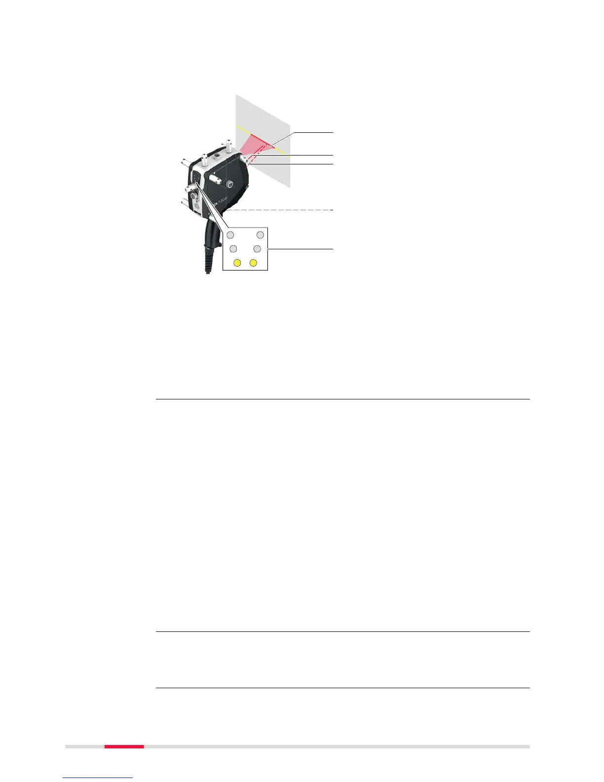
a Emerging laser beam
b Pilot beam (underneath
the scan line)
c Reflected beam
d Trigger button
e Stand-off indicator LED
The LEDs on the back side of the sensor also function as positioning aid:
•
The stand-off indicator LED indicates the distance between sensor and
measuring object.
•
The status LEDs indicate the status of the T‑Scan controller (ON/OFF)
and the measurement status of the T‑Scan and the Laser Tracker.
The data acquisition can be started with the trigger key on the handle of the
sensor.
The T‑Scan can be operated as a handheld scanner or can be mounted onto a
robot or machine to measure clouds of points. The T‑Scan works with the
Leica Absolute Tracker 6DOF system. The measurement range of the T‑Scan
depends on the Laser Tracker model that is used.
The Absolute Tracker controller synchronises all relevant system components
to a common time base.
On the centre of each face of the T‑Scan, a reflector is located. Together with
the marker LEDs, the reflectors represent the measurement targets of the
system. In order to describe the position and orientation of the T‑Scan in
relation to the Absolute Tracker system, six measurement parameters are
needed:
•
Three position parameters (Hz, V, D)
•
Three orientation parameters (w, j, k)
These parameters are determined by measurements with the Laser Tracker
(position) and the Measurement Camera (orientation).
•
Horizontal angle - Hz
•
Vertical angle - V
•
Distance - D
The Laser Tracker
6DOF system
Laser Tracker
parameter for 3D
position
22 Description of the System
 Loading...