7
Chapter 2Frame Mortise & Tenon Jig User Guide
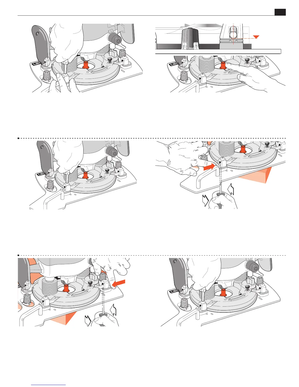
MOUNTING THE ROUTER
2-21 Using the hex screwdriver, turn down the four U-Post set-
screws until there is only very slight and even pressure on each
end of both rods. Leave the shim stops in the outer position.
2-22 Check that the rods are still centered in the rod holes
➀
and
check that the router collet can rotate without excessive binding in
the Sub-Base hole. Mandrel touching side of hole is OK; mandrel
binding tight is not! Move the router if required to allow mandrel
to rotate.
2-23 Tighten the top U-Post set-screws a little more securely to
hold the bars and router.
2-24 Slide the router/Sub-Base assembly on the corner of the
bench so that one U-Post bottom screw is overhanging the edge.
Loosen this screw just slightly (if necessary) to take any pressure
off the shim spacer above. Push the Shim spacer in to touch the
router base and, holding it in position against the router base,
firmly tighten this bottom screw.
2-25 Repeat this procedure at the other end of the same rod to
position the shim stop against the router base. Re-check the collet/
mandrel for relatively free rotation. Turn the router around on the
corner of the bench and repeat this procedure on the two U-Post
assemblies on the second rod.
2-26 Tighten the four U-Post set-screws to the rods. The hex driver has
high leverage so use common sense when tightening. The rods will bow
slightly. Objective: have the collet concentric to the bit hole; the four shim
stops providing secure side thrust security, and the U-Posts clamping the rods
which hold the router against the Leigh Sub-Base. Router /Sub-Base are now
a unit. Release the plunge; remove and store the mandrel. You’re set to go.