Objectives
1
__!gl!l!
2 - JW.,
.,......:.;
::t;;j
3:=;
~
.:.,-
4
5-
......
~~
s-
.......
~---~~-.
7-
s ;;,.;
;:;::;::;:::;:;::
22952-519 R
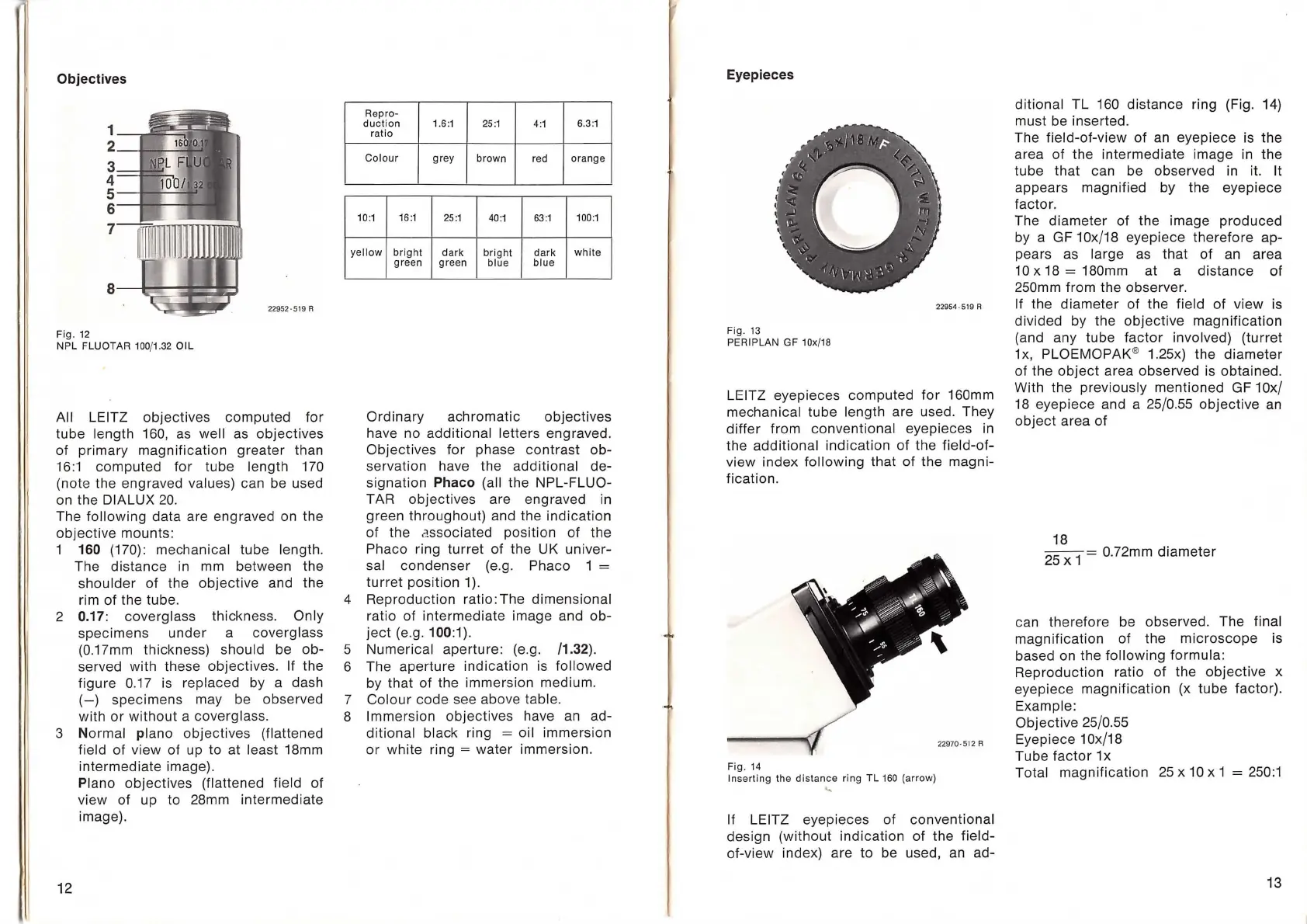
Fig.
12
NPL FLUOTAR
100
/1.
32
OIL
All LEITZ
objectives
computed
for
tube length 160, as well as
objectives
of primary
magnification
greater
than
16:1
computed
for
tube
length 170
(note the engraved values) can be used
on the DIALUX
20
.
The
following
data
are engraved on the
objective
mounts:
1 160 (170) : mechanical
tube
length.
The
distance
in
mm between the
shoulder
of
the
objective
and the
rim
of
the tube.
2
0.17:
coverglass
thickness. Only
specimens
under
a coverglass
(0
.17mm thickness)
should
be
ob-
served with these
objectives
. If the
figure
0.17 is replaced by a dash
(-)
specimens
may be observed
with
or
without
a coverglass.
3
Normal
piano
objectives
(flattened
field
of
view
of
up to at least 18mm
intermediate
image).
12
Piano
objectives
(flattened field
of
view
of
up to 28mm
intermediate
image).
Repro-
duction
1.6:1
25:1
4:1
6.3:1
ratio
Colo
ur
grey
brown
red
orange
10:1
16
:1
25
:1
40:1
63
:1
100
:1
y
ellow
bright
dark
bright
dark
white
green
gr
ee
n
blue
blue
Ordinary
achromatic
objectives
have no
additional
letters engraved.
Objectives
for
phase
contrast
ob-
servation have the
additional
de-
signation
Phaco (all the NPL-FLUO-
TAR
objectives
are engraved in
green
throughout)
and the indi
cation
of
the a
ssociated
position
of
the
Phaco ring
turret
of
the UK
univer-
sal
condenser
(e
.g. Phaco 1 =
turret
position
1 ).
4
Reproduction
ratio: The
dimensional
ratio
of
intermediate
image and
ob-
ject
(e.g. 100:1).
5
Numerical
aperture
: (e.g. /1.32).
6 The
aperture
indication
is
followed
by
that
of
the
immersion
medium.
7
Colour
code
see above table.
8 Immersion
objectives
have an ad-
ditional
black ring = oil
immersion
or
white
ring =
water
immersion.
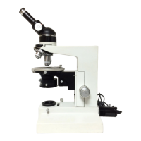
Eyepieces
22954-519 R
Fig. 13
PERIPLAN GF
10
x/
18
LEITZ
eyepieces
computed
for
160mm
mechanical
tube
length are used. They
differ
from
conventional
eyepieces
in
the
additional
indication
of
the
field-of-
view
inde
x
following
that
of
the
magni-
fication.
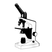
22970-512 R
Fi
g.
14
Inserting the distance ring TL
160
(arro
w)
"
If LEITZ eyepieces
of
conventional
design
(without
indication
of
the
field-
of-view index) are to be used, an ad-
ditional
TL
160
distance
ring (Fig. 14)
must be inserted.
The
field-of-view
of
an eyepiece is the
area
of
the
intermediate
image in the
tube
that
can be observed in
it
it
appears
magnified
by
the
eyepiece
factor.
The
diameter
of
the image
produced
by a GF 10x/18
eyepiece
therefore
ap-
pears as large as
that
of
an area
10 x 18 = 180mm at a
distance
of
250mm from the observer.
If the
diameter
of
the field
of
view
is
divided
by the
objective
magnification
(and any
tube
factor
involved)
(turret
1
x,
PLOEMOPAK
® 1.25x) the
diameter
of
the
object
area observed is
obtained.
With the previously
mentioned
GF 1
Ox/
18 eyepiece and a 25/0.55
objective
an
object
area
of
18
25
x
1
= 0.72mm
diameter
can
therefore
be observed. The final
magnification
of
the
microscope
is
based on the
following
formula:
Reproduction
ratio
of
the
objective
x
eyepiece
magnification
(x
tube
factor)
.
Example:
Objective
25
/0.55
Eyepiece 1 Ox/18
Tube
factor
1x
Total
magnification
25
x 10 x 1 = 250:1
13