Setting up phase contrast
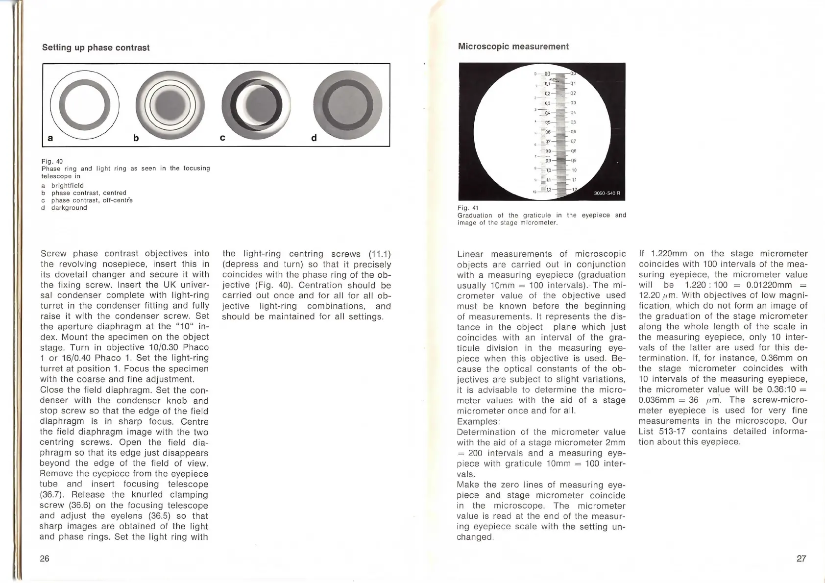
Fig.
40
Ph
ase ring and li
ght
ring
as
seen in the
focusing
telescope in
a
brightfield
b phase contrast, centred
c phase
cont
rast,
oil-centre
d
darkground
Screw
phase
contrast
objectives
into
the revolving
nosepiece
, insert
this
in
its dovetail
changer
and
secure
it
with
the fixing screw. Insert the UK univer-
sal
condenser
complete
with
light-ring
turret
in
the
condenser
fitting and fully
raise it
with
the
condenser
screw. Set
the
aperture
diaphragm
at the
"10"
in-
dex.
Mount
the specimen on the
object
stage.
Turn
in
ob
jectiv
e
10
/0.30 Phaco
1
or
16
/0.40 Phaco
1.
Set the
light-ring
turret
at
position
1.
Focus the specimen
with the
coarse
and fine adjustment.
Close the field diaphragm.
Set the
con-
denser
with the
condenser
knob
and
stop
screw
so
that
the edge
of
the field
diaphragm
is
in sharp focus. Centre
the field
diaphragm
image with the
two
centring
screws. Open the field
dia
-
phragm so
that
its edge
just
disappears
beyond the edge
of
the field
of
view.
Remove the eyepiece from the eyepiece
tube
and
insert
focusing
telescope
(36
.
7)
. Release the
knur
led
clamping
screw
(36.6) on the
focusing
telescope
and
adjust
the eyelens (36.5) so
that
sharp images are
obtained
of
the
light
and phase rings. Set the
light
ring with
26
the ligh
t-ring
centring
screws
(11.1)
(depress and turn) so
that
it
prec
isely
coincides
with the phase ring
of
the
ob-
jective
(Fig. 40).
Centrat
ion should be
carried
out
once
and
for
al l
for
all
ob
-
jective
light-ring
combinations,
and
should
be
maintained
for
all settings.
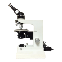
Microscopic measurement
Fig.
41
Graduation
ol
the
graticule
in the
eyepiece
and
image
ol
th
e sta
ge
micrometer.
Linear measurements of
microscopic
objects
are
carried
out
in
conjunction
with a measuring eyepiece (graduation
usually 1
Omm
= 100 intervals).· The mi-
crometer
value of the
objective
used
must be
known
before the
beginning
of
measurements. lt represents the
dis-
tance
in
the object plane wh i
ch
just
coincides
wit
h an interval
of
the
gra-
ticule
division in the measur
in
g eye-
piece when this
objective
is used. Be-
cause the
optica
l constants
of
the
ob-
jecti
ves are
subject
to
slight
variations,
it
is
advisable to
determine
the
micro
-
meter
values with the aid
of
a stage
micrometer
once
and
for
all.
E
xamp
les:
Determination
of
the
micrometer
value
with the aid
of
a stage
micrometer
2mm
= 200
inter
vals and a measuring eye-
piece with
graticule
10mm = 100 inter-
vals.
Make the zero lines
of
measuring eye-
piece and stage
micrometer
coincide
in
the
microscope.
The
micrometer
va
lue is read at the end
of
the measur-
ing eyepiece
scale
with the
setting
un-
changed.
If 1.220mm on the stage
micrometer
coincides
with
100 intervals of the mea-
suring
eyepiece, the
micrometer
value
wi
ll
be
1.220:
100 = 0.01220mm =
12.20 ,um. With
objectives
of
l
ow
magni-
fication, wh i
ch
do
not
form an image
of
the
graduation
of
the stage
micrometer
along
the
whole
length
of
the
sca
le
in
the measuring eyepiece, on ly
10
inter
-
va
ls
of
the l
atter
are used
for
this
de-
termination
. I
f,
for
instance, 0.36mm on
the stage
micrometer
coinc
ides
with
10
intervals
of
the measuring eyepiece,
the
micrometer
value wi
ll
be 0.36:10 =
0
.0
36mm =
36
,
um·.
The
screw-m
i
cro-
meter eyepiece
is
used
for
very fine
measurements
in
the
microscope.
Our
List 513-
17
contains
detailed
informa-
tion
about
this eyepiece.
27