o o
o o
o
22
22
2
TECHNICAL SPECIFICATIONSTECHNICAL SPECIFICATIONS
TECHNICAL SPECIFICATIONSTECHNICAL SPECIFICATIONS
TECHNICAL SPECIFICATIONS
Dimensions: (WxHxD) 483x88x445mm (2U)
Weight: 16Kg
Power Requirements: (230Vac±15% 50/60Hz) 1000VA
(115Vac±15% 50/60Hz) 1000VA
Output Power: (4Ω stereo/parallel) 2x 500Watts
(8Ω stereo/parallel) 2x 350Watts
(8Ω bridge) 1000Watts
(16Ω bridge) 700Watts
Max. Undistorted Out: (4Ω stereo/parallel) 126Vpp
(8Ω stereo/parallel) 149Vpp
(8Ω bridge) 250Vpp
Input Sensitivity: (constant sensitivity) 0.775Vrms (0dB)
(constant gain) 2.25Vrms (+9.2dB)
Input Impedance: (balanced) 30KΩ
(unbalanced) 15KΩ
Voltage Gain: (constant sensitivity) 35±0.5dB
(constant gain) 26±0.5dB
Slew Rate: 25V/µS
Damping Factor: (4Ω stereo/parallel) >400
(8Ω stereo/parallel) >800
Frequency Response (-0.2dB) 20Hz÷20KHz
at Full Power: (-3dB) 10Hz÷60KHz
IMD: (SMPTE 60Hz/7KHz 4:1) <0.1%
THD: (THD+N) <0.1%
S/N Ratio: (unweighted) >95dB
Crosstalk: (1KHz) >70dB
TEST PROCEDURES & ADJUSTMENTSTEST PROCEDURES & ADJUSTMENTS
TEST PROCEDURES & ADJUSTMENTSTEST PROCEDURES & ADJUSTMENTS
TEST PROCEDURES & ADJUSTMENTS
PrecautionPrecaution
PrecautionPrecaution
Precaution
➭ To prevent short circuit during any test,
the oscilloscope must bethe oscilloscope must be
the oscilloscope must bethe oscilloscope must be
the oscilloscope must be
EARTH insulatedEARTH insulated
EARTH insulatedEARTH insulated
EARTH insulated, this occurs because some test require to connect its
probe to the amplifier output, non-compliance may cause damages to
oscilloscope inputs circuitry.
➭ Before removing or installing any modules and connectors,
disconnectdisconnect
disconnectdisconnect
disconnect
the amplifier from AC MAINSthe amplifier from AC MAINS
the amplifier from AC MAINSthe amplifier from AC MAINS
the amplifier from AC MAINS and measure the DC supply voltages
across each of the power suppliy capacitors. If your measurement on any
of the caps is greater than 10Vdc, connect a 100Ω 100W resistor across
the applicable caps to discharge them for your safety. Remember to
remove the discharge resistor immediately after discharging caps.
Do notDo not
Do notDo not
Do not
power up the amplifier with the discharge resistor connectedpower up the amplifier with the discharge resistor connected
power up the amplifier with the discharge resistor connectedpower up the amplifier with the discharge resistor connected
power up the amplifier with the discharge resistor connected.
➭ Read these notes entirely before proceeding to any operation. These
notes are not comprehensive of all damages that possibly occur, but
includes some specifically advices, checks and adjustments relative to
this amplifier.
RemarksRemarks
RemarksRemarks
Remarks
➭ The output coupled transistors TR6-TR11 (MJ15022/B) and TR16-TR22
(MJ15023/B) are factory selected on V
BE
and V
BREAKDOWN
(I
EC0<
-6.6mA at
V
(BR)CE0
=11V for NPN and I
EC0
<6.6mA at V
(BR)CE0
=-11V for PNP)
The selection is marked by a red digit (from 0 to B) representative of V
BE
forward voltage categories, these are subdivided in 12 steps of 30mV
each.
Only selected transistors must be used when replacing TR6-TR11 orOnly selected transistors must be used when replacing TR6-TR11 or
Only selected transistors must be used when replacing TR6-TR11 orOnly selected transistors must be used when replacing TR6-TR11 or
Only selected transistors must be used when replacing TR6-TR11 or
TR16-TR22 and every coupled transistors must have the same digit.TR16-TR22 and every coupled transistors must have the same digit.
TR16-TR22 and every coupled transistors must have the same digit.TR16-TR22 and every coupled transistors must have the same digit.
TR16-TR22 and every coupled transistors must have the same digit.
➭ The power supply utilizes a dual bipolar DC rail configuration with low and
high voltages; one positive and one negative low rail (+/-Vcc1) and one
positive and one negative high rail (+/-Vcc2).
Visual CheckVisual Check
Visual CheckVisual Check
Visual Check
➭ Use compressed air to clear dust in the amplifier chassis.
➭ Before proceed to supply the amplifier check visually the internal assem-
bly, if appears an evident damage find the most possible reasons that
cause it.
➭ Check the wiring cables for possible interruptions or shorts.
➭ If the damage has burnt a printed circuit board don’t try to repair it, re-
place with a new one.
Test InstrumentTest Instrument
Test InstrumentTest Instrument
Test Instrument
➭ Audio Generator
➭ Dual Trace Oscilloscope
➭ Digital Multimeter
➭ 2Ω 2000W, 4Ω 1000W, 8Ω 1000W, 100Ω 100W resistors
➭ Variac
➭ Temperature Meter
SetupSetup
SetupSetup
Setup
➭ Connect the Variac between the PROTECTION board and the TF1 and
TF2 transformers and set it at zero voltage.
➭ Set the amplifier in STEREO MODE and turn full clockwise the LEVEL
potentiometers.
➭ Connect the audio generator to the channel inputs and set it to 1KHz
775mV
RMS
(0dB) sinusoidal signal.
➭ Insert the temperature meter through the IC1 interstice located at centre
of heatsink.
➭ The procedures that follow must be executed subsequently in the order
specified.
Supply CheckSupply Check
Supply CheckSupply Check
Supply Check
➭ Remove the transformer secondary fuses (located on FUSE board), set
the Variac to the nominal mains voltage, check with the Multimeter the
phase opposition between the secondaries of the two transformers (F1-
F2,F3-F4), if not, verify the primary connections (T1÷T4 on Protections
Board).
➭ Verify the AC supply voltages: F1-F2=72±2Vac F3-F4=128±3Vac.
➭ Re-set the Variac at zero voltage, turn off the amplifier and put the fuses
back on its holders.
➭ Connect the oscilloscope probes CH1/2 to the channel outputs, set both
to 20V/div. 200µS/div.
➭ Set up the Variac slowly monitoring the Outputs with the oscilloscope
CH1/2 connected, it should display the sinusoidal input signal amplified
with no distortions, if a distortion occur check the Driver and the Power
Boards as suggested in the ADVICES section.
➭ If the protection trips, turn off the amplifier, wait some minutes and dis-
connect the supplies from the outputs modules (CN1 - CN2 - CN7 - CN8
on POWER boards), continue to check the supplies.
➭
CAUTION: Before re-connecting the output modules to the supplies,CAUTION: Before re-connecting the output modules to the supplies,
CAUTION: Before re-connecting the output modules to the supplies,CAUTION: Before re-connecting the output modules to the supplies,
CAUTION: Before re-connecting the output modules to the supplies,
you must have the capacitors discharged for your safety: connect ayou must have the capacitors discharged for your safety: connect a
you must have the capacitors discharged for your safety: connect ayou must have the capacitors discharged for your safety: connect a
you must have the capacitors discharged for your safety: connect a
100100
100100
100
ΩΩ
ΩΩ
Ω
100W resistor across the caps and remove the resistor just 100W resistor across the caps and remove the resistor just
100W resistor across the caps and remove the resistor just 100W resistor across the caps and remove the resistor just
100W resistor across the caps and remove the resistor just
after they are discharged.after they are discharged.
after they are discharged.after they are discharged.
after they are discharged.
➭ Finally verify the DC supplies on Supply Board:
CN6 (+Vcc2) =+89.5±2Vdc
CN8 (+Vcc1) =+50±1.5Vdc
CN7 (-Vcc1) =-50±1.5Vdc
CN2 (-Vcc2) =-89.5±2Vdc
on Protections Board:
CN2 pin3 =+27±1Vdc
CN3 pin3 =-27±1Vdc
CN1 pin4-5-6 =+13.8±1Vdc
CN1 pin1-2-3 =-13.8±1Vdc
➭ If one or more voltages don’t correspond, check the rectifiers, capacitors
and transformers disconnecting them from circuitry, refer to schematics.
Channels CheckChannels Check
Channels CheckChannels Check
Channels Check
➭ The channel A is facing the front and channel B the rear of the chassis.
➭ These procedures are intended for one channel at a time, repeat these
operation for the other channel.
➭ Verify, with the Multimeter, the insulation between the heatsink and the
transistors collectors.
➭
SETUP:SETUP:
SETUP:SETUP:
SETUP:
Connect the CH1 scope GND clip to CN5 (GND terminal).
Connect the CH1 probe tip to CN6 (AMP output).
Connect the CH2 probe tip to D2 cathode on POWER board.
Set the LEVEL potentiometers full clockwise.
The load resistor is disconnected.
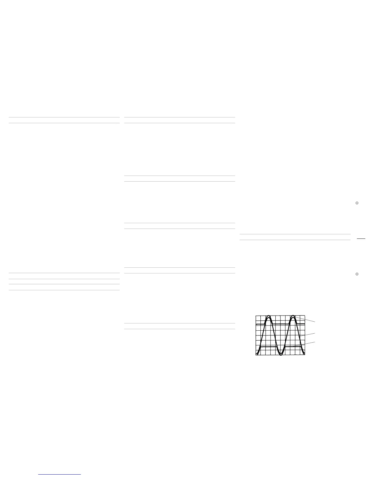
➭
INITIAL TEST:INITIAL TEST:
INITIAL TEST:INITIAL TEST:
INITIAL TEST:
Increase slowly the Variac. The channel output signals must be symmetri-
cal respect the GND without visible distortion and oscillation as shown in
Fig.1 Trace A
. If there is a distortion read the section ADVICES and
proceed to check the other channel.
Verify that, when the heatsink temperature is less 50°c, the cooling fan
Fig. 1Fig. 1
Fig. 1Fig. 1
Fig. 1
Trace B (20V/div.)
Trace A (20V/div.)
Trace C (20V/div.)
 Loading...