Lemon Microbrick Reference Guide
Page 6 of 20
If you are using a transmitter with seven channels or less and thus do not have access to Master Gain (channel
8), stabilization will work normally but you will not have the ability to adjust stabilizer gain in flight. If you have
an eight or more channel transmitter, see “Master Gain” on page 16
It’s a good idea to set up the receiver and any external servos on the bench and test them before installing in the
model.
1. Set up the transmitter
If using a computer transmitter, set up a new ACRO model. Omit any elevon (delta) or V-tail mixing.
Make sure
control throws (end points/limits) are set to 100% (If using an open-source firmware transmitters, see the
separate “Using the Microbrick with other Transmitters” document).
2. Bind the receiver
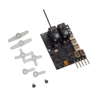
The receiver needs to be bound to the transmitter before it will operate. The push button provides a convenient
and reliable method of binding. Hold the button in while connecting power. The red LED on the bottom of the
board will start flashing rapidly to indicate that the receiver is in bind mode. Release the button.
Now put the transmitter into bind mode and go through the bind procedure. If you have difficulty binding, move
the transmitter further away from the Microbrick. The sensitive receiver in the Microbrick can get overloaded at
close range, which may inhibit the bind process. Normally, the receiver will bind at 1-2m, but sometimes it needs
to be 3-4m from the transmitter. Nearby metal objects such as a furnace, fence or vehicle can also prevent
binding, as can a Wi-Fi router or nearby active RC transmitters.
After the receiver is bound, set the transmitter elevator and rudder sticks and trims to neutral. With the system
powered up, fit the two output arms as closely as possible to 90˚ to the servo center line and attach with the
retaining screws.
3. Test the receiver on the bench in non-stabilized mode
Turn on the transmitter and then the receiver. Turn OFF stabilization. To do this, either:
• Turn all three of the on-board gain pots fully anticlockwise with a small screwdriver. This sets the
stabilization gains to essentially zero.
• OR ensure channel 5 is set to 100% (red and green LEDs both ON).
• OR set channel 8 (if available) to -150%.
Test all servos for smooth operation.
At this point, it’s a good idea to perform a range check to verify that the system is working properly.
4. Test the receiver in stabilized mode (if applicable)
Set the gain pots to mid-point (12 o’clock). Set the channel 5 switch to stabilization ON (-100%). Only the green
LED should be lit.
Briefly check that the red LED lights when you move the channel 5 switch to OFF (100%). Having both red and
green LEDs illuminated indicates that the stabilizer is NOT operating.