Page 26
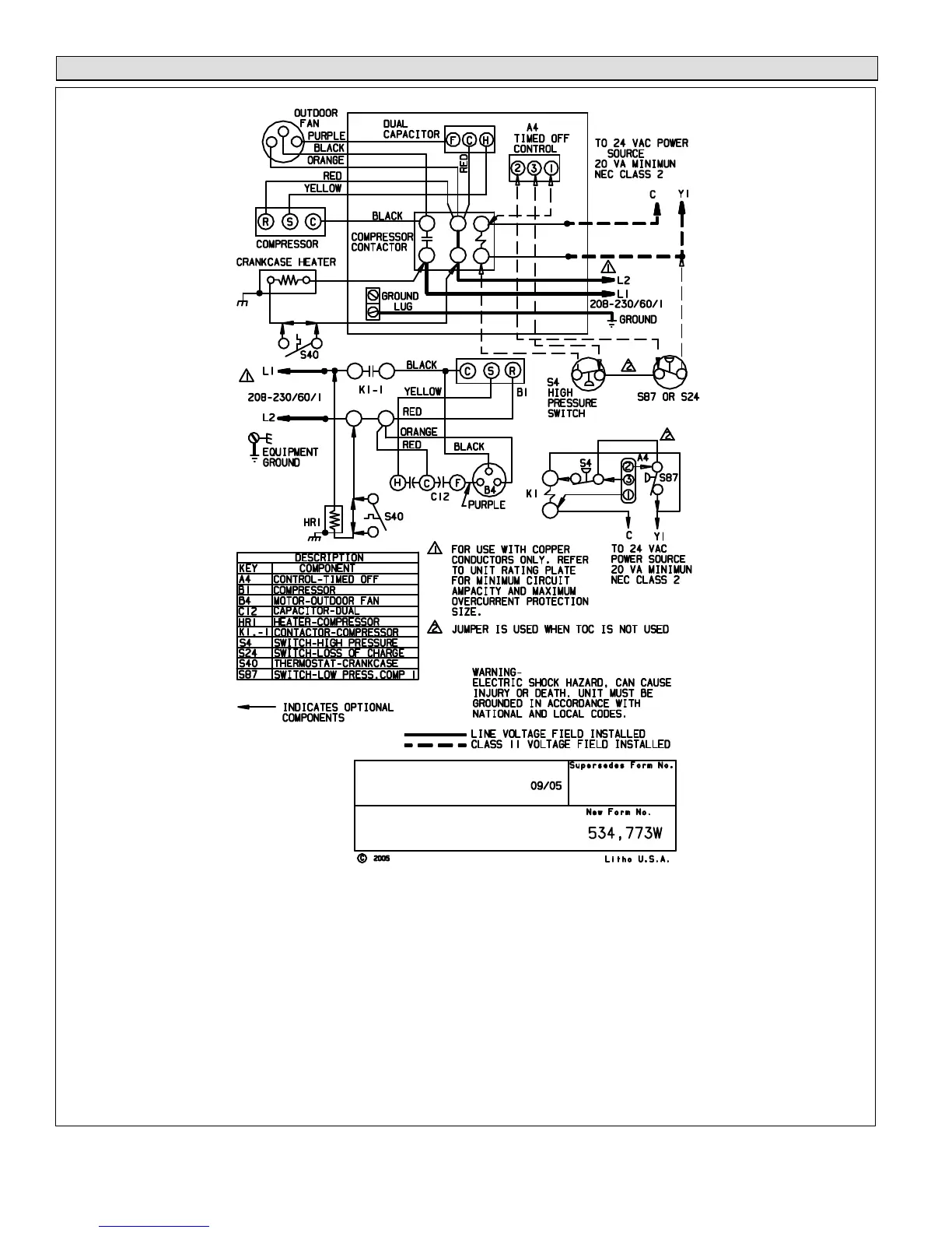
Sequence of Operations
NOTE- The thermostat used may be electromechanical or electronic.
NOTE- Transformer in indoor unit supplies power (24 VAC) to the thermostat and outdoor unit controls.
COOLING:
1- Cooling demand initiates at Y1 in the thermostat.
2- 24VAC from indoor unit (Y1) energizes the TOC timed off control (if used) which energizes contactor K1
(provided S4 high pressure switch is closed).
3- K1‐1 N.O. closes, energizing compressor (B1) and outdoor fan motor (B4).
4- Compressor (B1) and outdoor fan motor (B4) begin immediate operation..
END OF COOLING DEMAND:
5- Cooling demand is satisfied. Terminal Y1 is de‐energized .
6- Compressor contactor K1 is de‐energized.
7- K1‐1 opens and compressor (B1) and outdoor fan motor (B4) are de‐energized and stop immediately.
Figure 14. Use for 13ACX-XXX-230-01 through -10
 Loading...