# 48306B006 Page 9
Leak Testing
After the line set has been connected to the indoor and
outdoor units, the line set connections and indoor unit
must be checked for leaks.
To Close Liquid or Suction Line Service Valve:
1. Remove the stem cap with an adjustable wrench.
2. Use a service wrench with a hex-head extension to turn
the stem clockwise to seat the valve. Tighten firmly.
3. Replace the stem cap. Tighten finger tight, then
tighten an additional 1/6 turn.
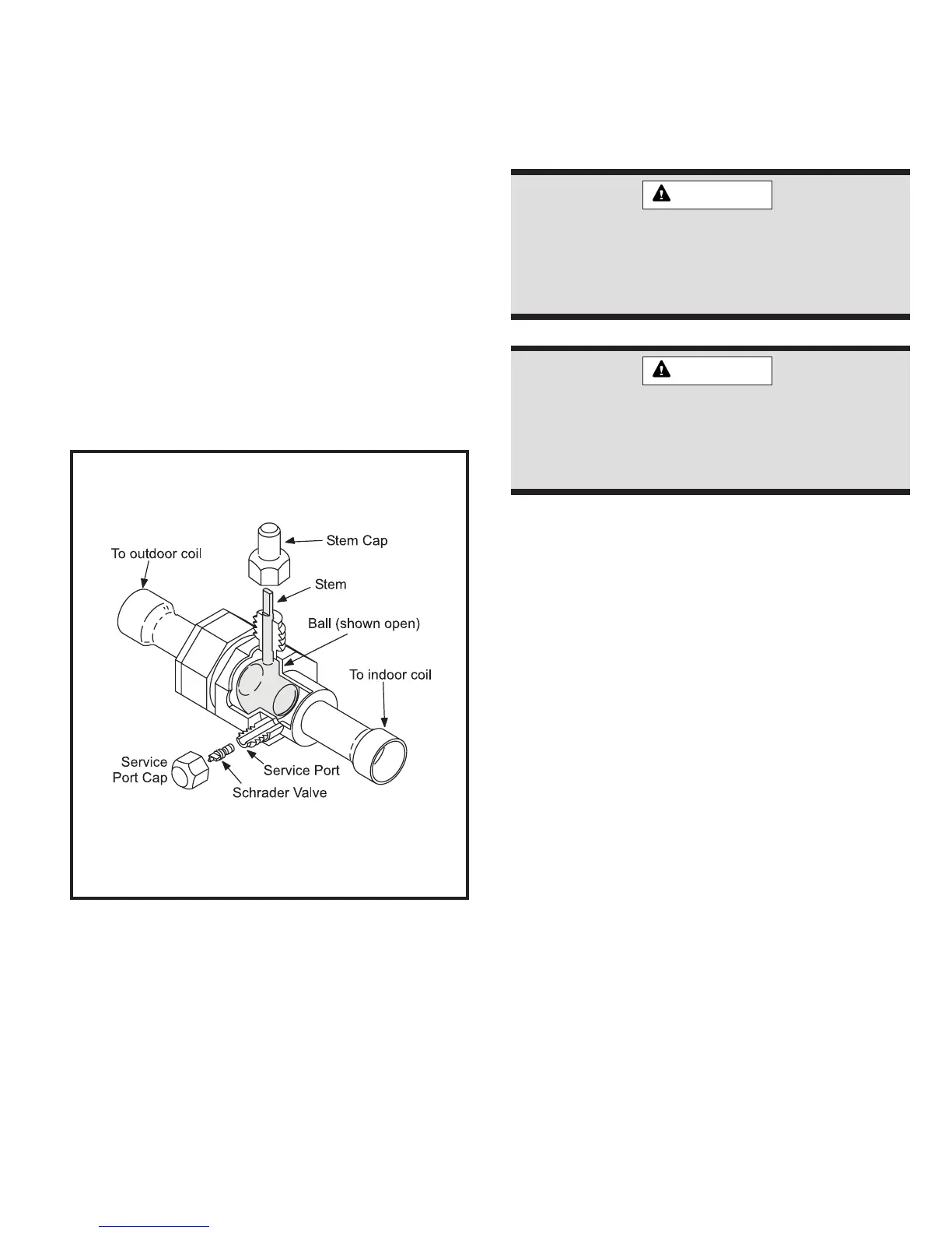
Suction Line (Ball Type) Service Valve
Suction line (ball type) service valves function the same
way as the other valves; the difference is in the construc-
tion (see Figure 11).
The ball valve is equipped with a service port with a
factory-installed Schrader valve. A service port cap
protects the Schrader valve from contamination and
serves as the primary seal.
Ball Type Service Valve
(Valve Open)
Figure 11
Use adjustable wrench. To open, rotate stem
counterclockwise 1/4 turn (90°). To close, rotate
stem clockwise 1/4 turn (90°).
Refrigerant can be harmful if inhaled. Refrigerant
must always be used and recovered responsibly.
Incorrect or irresponsible use of refrigerant can
result in personal injury or death.
WARNING
Never use oxygen to pressurize refrigeration
or air conditioning systems. Oxygen will ex-
plode on contact with oil and could cause
personal injury or death.
WARNING
Using an Electronic Leak Detector
1. Connect the high pressure hose of the manifold
gauge set to the suction valve service port. (Normally
the high pressure hose is connected to the liquid line
port; however, connecting it to the suction ports helps
to protect the manifold gauge set from damage
caused by high pressure.)
2. With both manifold valves closed, connect the cylin-
der of HCFC-22 refrigerant. Open the valve on the
HCFC-22 cylinder (vapor only).
3. Open the high pressure side of the manifold to allow
HCFC-22 into the line set and indoor unit. Weigh in a
trace amount of HCFC-22. (A trace amount is a
maximum of 2 oz. of refrigerant or 3 lbs. pressure.)
Close the valve on the HCFC-22 cylinder and the
valve on the high pressure side of the manifold gauge
set. Disconnect the HCFC-22 cylinder.
4. Connect a cylinder of nitrogen with a pressure regulat-
ing valve to the center port of the manifold gauge set.
When using high pressure gas such as nitrogen
for this purpose, be sure to use a regulator that
can control the pressure down to 1 or 2 psig.
5. Adjust nitrogen pressure to 150 psig. Open the valve
on the high side of the manifold gauge set to pressur-
ize the line set and the indoor coil.
Evacuation
Evacuating the system of noncondensables is critical for
proper operation of the unit. Noncondensables are defined
 Loading...