Page 18
F−Secondary Limit Controls (S21)
The secondary limit (S21) on 80MGF units is located in the
blower compartment in the back side of the blower housing.
When excess heat is sensed in the heat blower compartment,
the limit will open. If the limit is tripped, the furnace control en-
ergizes the supply air blower and closes the gas valve. The
limit automatically resets when unit temperature returns to
normal. The switch is factory set and cannot be adjusted.
Two limits are supplied in each furnace and each limit is a
different style (figures 15 and 16). The setpoint will be
printed on the side of the limit. If stick limit (Figure 16) suf-
fers from nuisance trips and the furnace is in the horizontal
position, replace with limit kit no. 50L98.
INSULATING COVER (s)
FIGURE 16
LIMIT CONTROL (S21) (S10)
FOR 80MGF SERIES UNITS
SPADE CONNECTORS
INSULATING COVER
LIMIT
LIMIT
THIS TYPE AUTO-RESET LIMIT IS
USED FOR THE LEFT SECONDARY
LIMIT (S21) (see FIGURE 13)
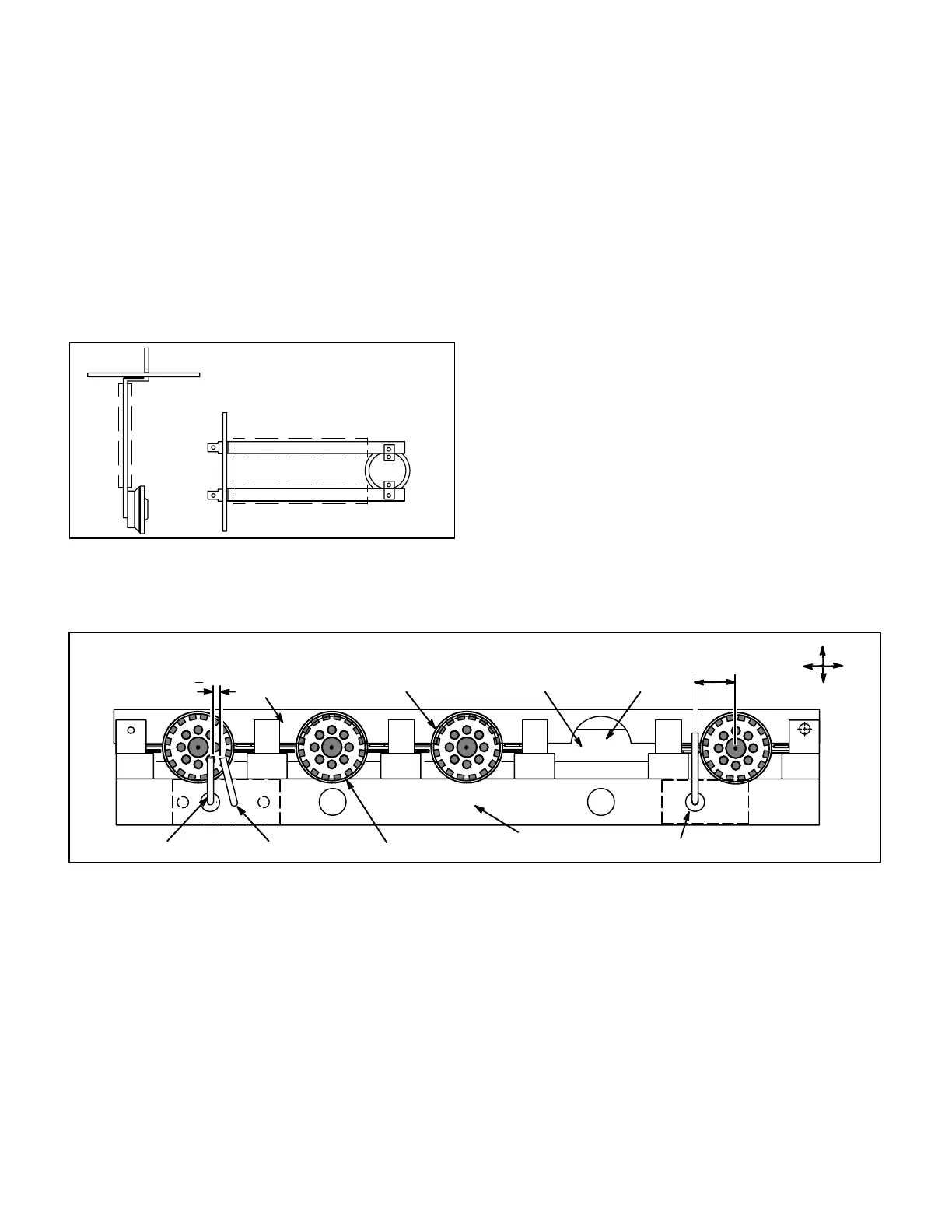
G−Spark Electrode and Flame Sensor
(Models with EGC or Ram control only)
Figure 17 shows the arrangement of flame sensor, spark
electrode and burners. The Ram and EGC ignition control
uses direct spark to ignite the rightmost burner and the
burners cross-light to the left. The flame sensor uses flame
rectification to sense combustion. A flame retention ring in
the end of each burner is used to maintain correct flame
length and shape and to keep the flame from lifting off the
burner head.
Figure 18 shows the gap between tip of the electrodes and
the burner surface.
H−Gas Valve
The 80MGF uses a gas valve manufactured by Honey-
well or WhiteRodgers. The valve is internally redundant to
assure safety shut−off. If the gas valve must be replaced,
the same type valve must be used.
24VAC terminals and gas control knob are located on top of
the valve. All terminals on the gas valve are connected to
wires from the electronic ignition control. 24V applied to the
terminals energizes the valve.
Inlet and outlet pressure taps are located on the valve. A regu-
lator adjustment screw is located on the valve. Refer to figures
19 or 20 for location of valve features.
An LPG changeover kit is available from Lennox. The kit in-
cludes burner orifices and a regulator conversion kit.
FIGURE 17
TYPICAL BURNER/ELECTRODE ORIENTATION
DIRECT SPARK MODELS ONLY
BURNER
FLAME RETENTION RING
UPPER BURNER
MOUNTING RAIL
LOWER BURNER
MOUNTING RAIL
MANIFOLD ORIFICE
Right Left
Top
Bottom
FLAME SENSOR
SPARK ELECTRODE
GROUND
1/8"(+1/64")
23/32 in.
(18 mm)

 Loading...


