Page 11
Thermostat Connection
Thermostat wires are connected to the terminal strip
found on the EGCĆ2 control board.
Troubleshooting
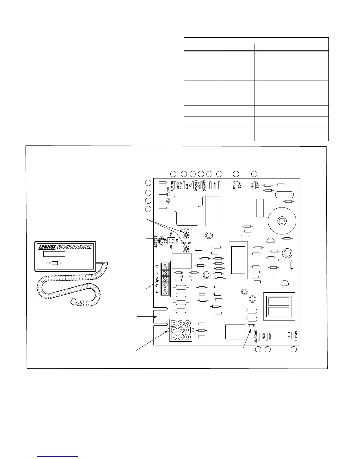
The EGCĆ2 control board is equipped with two diagnostic
green LEDs to indicate the mode of failure. The LED lights
are marked DIAG #1 and DIAG #2. The codes are given in
table 5.
A slotted edge connector is also provided for the Lennox
Diagnostic Module (part number 11K75). See figure 10.
When connected to the EGCĆ2 control board, the module disĆ
plays (in words) the diagnostic condition.
TABLE 5
EGCĆ2 DIAGNOSTIC CODES
DIAG #2 DIAG #1 DIagnostic Condition
Simultaneous
Flash
Simultaneous
Flash
Power ON". Normal Operation. InĆ
creased flash rate indicates there
is a heating demand.
On Flash
Primary or Secondary
Limit Switch Open.
AutoĆReset Switch.
Flash Off
Pressure Switch Watchguard,
pressure switch opened during
operation.
Alternate
Flash
Alternate Flash
Watchguard, burners
failed to ignite.
Off Flash
Flame sensed without
valve energized.
Flash On
RollĆout Switch Open.
ManualĆReset Switch.
Continuous
On
Continuous On
Circuit board selfĆcheck failure or
ignition/blower control
is wired incorrectly.
EDGE
CONNECTION
FIGURE 10
80UHG-1 MODEL INTEGRATED CONTROL (EGC-2)
(Shown as installed in horizontal left hand application)
(See tables 6 and 3 for terminal designations)
THERMOSTAT
TERMINAL STRIP
(DETACHABLE)
BLOWER TIME
ADJUSTMENT
JUMPER
DIAGNOSTIC MODULE
DIAGNOSTIC LEDS
DIAGNOSTIC CODE ERASE JUMPER
(Remove power to control and short pins for
10 seconds to erase previous code.)
24VAC
PLUG P20
5
6
7
8 9 10 11 12 13 15
123
4
14
1
2
3
4
6
5
7
8
9
 Loading...


