Page 4
The thermostat is now ready for operation. Turn on
power to the thermostat and refer to the appropriate 5/2
Programmable Thermostat Operation Manual.
11. Remove the clear protective film from the face of the
thermostat display.
NOTE - After this film is removed, some dark streaks or lines
may temporarily appear on the display. These are normal
and should disappear within a few minutes.
Removing Thermostat
The thermostat hinges on tabs on the top of the sub-base.
After installation is complete, no tool is needed to remove
the thermostat from the sub-base. Pivot the bottom of the
thermostat outward (releasing the snaps), then lift up to
remove.
Thermostat Terminals
On Lennox Commercial heat pumps listed below the
reversing valve is controlled by W1 through a transfer relay.
Commercial packaged heat pumps (2-20 tons)
Commercial split heat pump systems (7-10 tons)
NOTE - Not for use with small 3-5 ton split heat pump
systems.
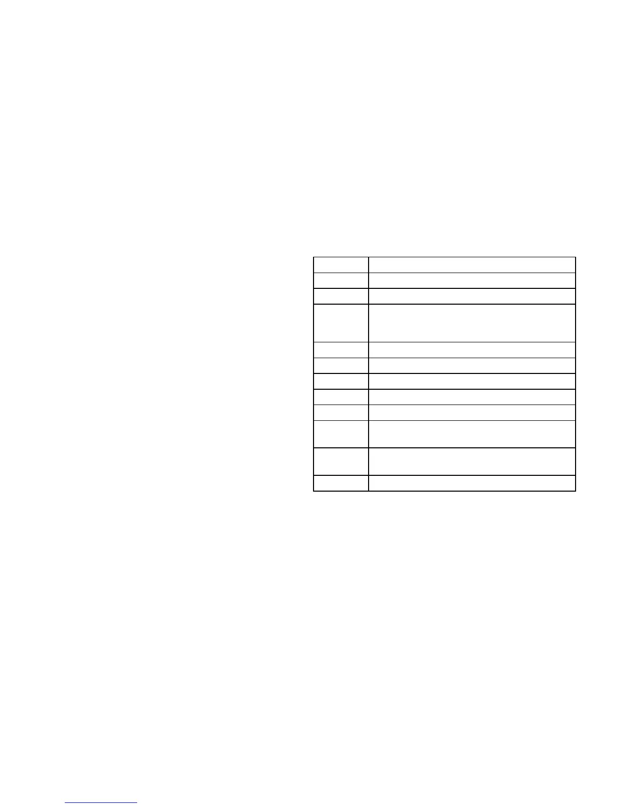
Table 1. Terminal Designations
Terminal Description
R 24VAC
Y1 Compressor Stage 1 cooling
W1 Stage 1 heating (gas, electric or heat pump
heating on certain size and types
systems*.)
Y2 Compressor Stage 2 cooling
W2 Stage 2 heating (electric)
G Fan
L Service indicator
C Common 24VAC
T Remote Indoor Temperature Sensor
connection 1
T Remote Indoor Temperature Sensor
connection 2
OC Occupancy output (economizer)