EasyManua.ls Logo

Lennox ComfortSense 8500 Series User Manual

Lennox ComfortSense 8500 Series
28 pages
To Next Page IconTo Next Page
Page #1 background imageLoading...
Page #1 background image
507611-03
7/2019
Supersedes 11/2018
Installation and Setup
Guide
ComfortSense
®
8500 Commercial
Programmable Thermostat Series -
Question and Answer IconNeed help?

Do you have a question about the Lennox ComfortSense 8500 Series and is the answer not in the manual?

Lennox ComfortSense 8500 Series Specifications

General IconGeneral
BrandLennox
ModelComfortSense 8500 Series
CategoryThermostat
LanguageEnglish

Summary

CS8500 Features Overview

Product Description

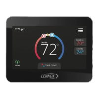
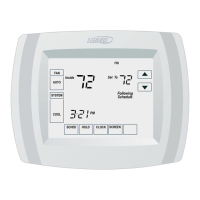
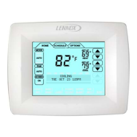
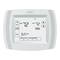
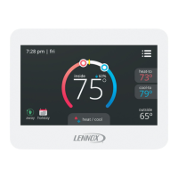
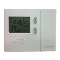
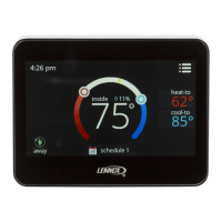
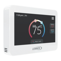
Commercial, electronic, 7-day, multi-stage, programmable touchscreen thermostat.

Installation Procedures

Back Plate Removal

Open case with screwdriver to separate unit from base.

Sensor Location Selection

Choose location 5 ft above floor with good air circulation.

Installation Site Restrictions

Avoid drafts, heat sources, and enclosed areas for accurate sensing.

Wall Plate Mounting

Use wall plate as template for wiring cutout and anchor drilling.

Terminal Connections and Wiring

Communication S-Bus Wiring

Terminals CM- and CM+ use S-Bus wiring per Table 2.

Terminal Function Definitions

Details R, TT, OC OC, CM- CM+, C terminals and their purposes.

CS8500 Wiring Guide

Controller Wiring

Connect wiring between CS8500 and applicable controller.

Temperature Sensor Installation

Occupancy Sensor Installation

CS8500 Initial Setup Procedures

Technician Settings Access

Access via MENU > TECHNICIAN SETTINGS (PIN 864).

S-Bus Address Synchronization

Set CS8500 S-Bus address to match rooftop unit.

Smart Hub Operation Setting

Set Smart Hub (central hub or NCP) to ON/OFF.

BACnet Integration with M3 Controller

M3 Unit Controller Configuration Steps

CS8500 Sensor Failure Handling

CS8500 Troubleshooting Guide

Power Supply Verification

Ensure 24VAC is supplied to the CS8500.

S-Bus Address Matching

Verify CS8500 S-Bus address matches M2/M3 controller address.

Communication Cable Inspection

Check communication cable wiring for issues.

M3 Unit Controller Temperature Limits

Parameter Settings Based on System Configuration

CS8500 Fault Status Indicators

Error Codes and Reminders

Built-In Temperature Sensor Errors

Temp sensor reads outside normal range; system displays '--'.

Remote Temperature Sensor Errors

External sensor reads outside normal range; unit switches to internal sensor.

System Error Diagnostics

EEPROM and Memory Errors

Errors during power-on or operating mode; may restore factory defaults.

Humidity Sensor Malfunctions

Invalid or out-of-range humidity readings; home screen displays '--'.

Sensor and Communication Errors

CO2 Sensor Malfunctions

Invalid or out-of-range CO2 readings; home screen displays '--'.

Communication Startup Errors

Detected failed (offline) state; requires listening for valid message.

RTU Compressor Lock Errors

Errors displayed in notification/technician screens; contact service.

System Event Reminders

RTU Lock and Fault Reminders

Errors displayed in notification/technician screens; check RTU state.

Related product manuals