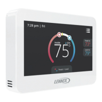
g. Route the CS8500 and outdoor tempera-
ture sensor (optional) wiring from wall
through center openings on wall plate (use
is optional) and back plate (see “Figure 3.
Wall Plate (optional)
Thermostat
Back Plate
Run thermostat wire
through openings
Figure 3. Route Wiring
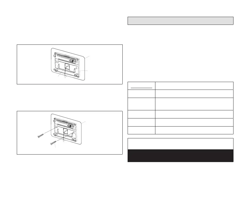
h. Secure back plate and wall plate (option-
al) to wall with the two provided mounting
screws.
Wall Plate (optional)
Thermostat
Back Plate
Screw
Figure 4. Secure Back Plate
NOTE: Remember to seal the hole in the wall with
a suitable material to prevent drafts from
entering the zone sensor case. Not doing
so could aect the internal temperature
and humidity sensors.
Terminal Connections
External sensors use standard thermostat wiring;
and may be wired using two wires of a multiple wire
cable. Wire run should not exceed 300 feet (100m).
-
enced in “Table 2. Twisted Pair Communication Wir-
ing (S-Bus - Yellow)” on page 4.
Table 3. Twisted Pair Communication Wiring
(S-Bus - Yellow)
Terminals Purpose
R
24VAC
T T
External indoor temperature sensor
OC OC
Occupancy sensor
S-Bus communication
C
24VAC common
IMPORTANT!
Damage to the ComfortSense 8500 may occur if
24VAC polarity is not maintained.
 Loading...