7
Wiring CS8500 (with or without CO Sensor)
Below are the terminal designations and a general
description of their purpose.
1. Connect wiring between CS8500 and
applicable controller.
2. Connect external sensors if applicable.
3. Seal the hole in the wall with a suitable material
to prevent drafts from entering the CS8500
case.
4.
type and test system.
24VAC transformer with
overcurrent protection
required (6.5VA/Zone)
ComfortSense 8500
Figure 5. CS8500 Connections (both versions)
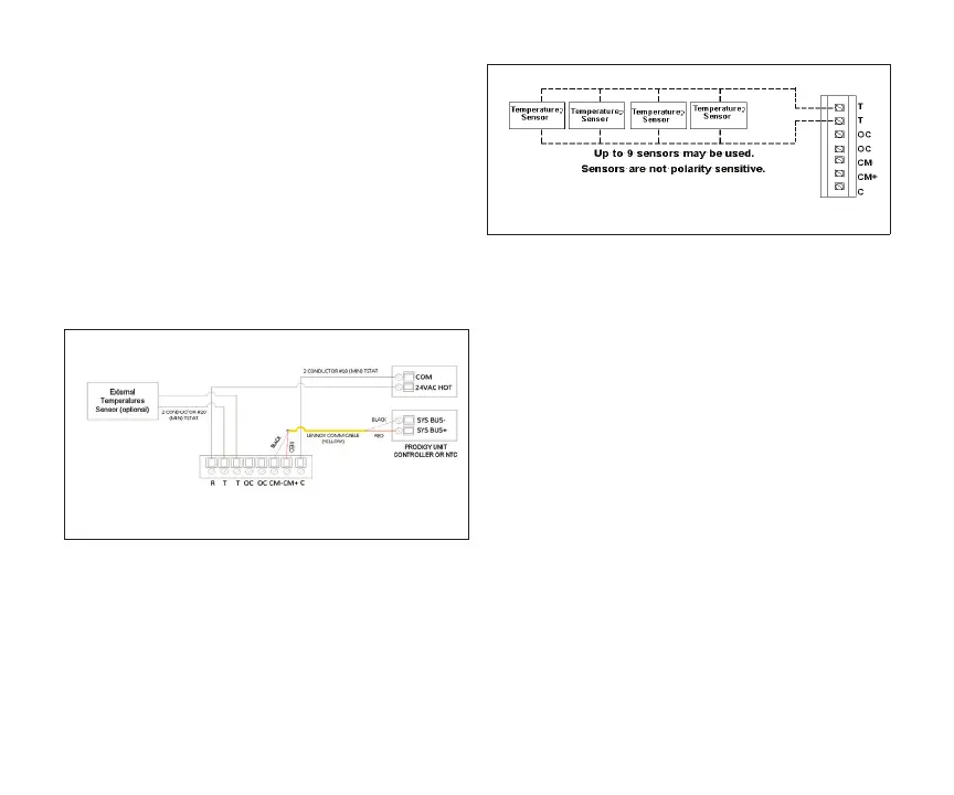
Installing Indoor Temperature Sensors
Wire external sensors as illustrated below. Up to
nine sensors may be used in averaging sensor
sensitive.
Figure 6. Temperature Sensor Wiring
(parallel)
The CS8500 will calculate the average temperature
readings from all connected external temperature
sensors. If any of the sensors malfunction, they
may still report a temperature value. Only when the
average value of the connected temperature sen-
sors including any malfunction sensor(s) is lower
than -40°F, or higher than 158°F, will the CS8500
determine that an external temperature sensor(s)
has failed and switch automatically to the CS8500’s
internal temperature sensor. A error message will be
displayed on the home screen and under the noti-
sensor” error.
Installing Occupancy Sensor
The occupancy sensor will output:
• 24VAC in occupied mode.
• 0VAC in unoccupied mode.
 Loading...