9
M1 / M2 Unit Controller Setup
From the main menu, perform the following naviga-
tion through the menus to set the S-Bus address for
L Connection.
Go to: Settings > Control > Guided Setup > Enter
Advanced Guide Setup > Set Control >
LCONN > ADDR
Enter the S-Bus address for L Connection. Once
done select the Set option to save the settings.
M1 / M2 Unit Controller - Control Mode and
Backup Set Points Setup
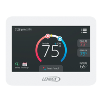
The following unit controller ECTOs must be set
when using the CS8500.
ECTO 5.27 - This is use and depends on the avail-
able sensors on the CS8500. Room temperature
reading is standard on all models. The following set-
ting instructs the M1/M2 unit controller what source
to get zone temperature, CO, and indoor RH input.
• 2 = Room temperature (A2)
•
• 10 = Room temperature and indoor RH (A91)
• 11 = Room temperature, IAQ, and indoor RH
ECTO 6.01
controller control mode and back-up set points to
use. Options are:
• 1 = Zone sensor mode with no backup.
• 2 = Zone sensor mode with local sensor backup.
• 3 = Zone sensor mode with return air sensor
backup.
M3 Unit Controller Setup
From the main menu, perform the following naviga-
tion through the menus to set the S-Bus address for
L Connection.
1. Go to SETUP > NETWORK INTEGRATION >
L-CONNECTION > LCONN ADDRESS.
2. Enter the desired LCONN ADDRESS (S-Bus)
and select SAVE to continue.
3. Set CONTROL MODE = ROOM SENSOR and
select SAVE to continue.
4. NETWORK SENSOR CO2 (if equipped)
needs to be set to YES (if choosing CO from
CS8500). Select SAVE to continue.
5. RELATIVE HUMIDITY needs to be set to YES
(if choosing RH from CS8500). Select SAVE
to continue.
TEMPERATURE will need to be set to YES (if
choosing temperature from CS8500).
7.
questions until it returns you to the NETWORK
INTEGRATION menu option.
NOTE: Once the conguration is saved, then
S-Bus communication will be lost and
alarm 110 (low priority) will be raised. This
will be cleared automatically when any
demand goes to M2/M3.
 Loading...
