2. Connect primary drain line connection to the primary
drain pan connection, The primary drain connection is
flush with the bottom of the inside of the pan,
Secondary connection is raised above the bottom of
the inside of the pan.
NOTE - When making drain fitting connections
to the drain pan, hand tighten the fitting and use
a sealant, Over-tightening the fittings can split
connections on the drain pan,
3. If the auxiliary drain line is to be used, remove the plug
and route the drain line so that water draining from the
outlet will be easily noticed by the homeowner. The
auxiliary drain line does not required venting or a trap.
Refer to local codes,
4. After removal of drain pan plugs, check the drain port
to see if holes have been drilled. If not drilled, use a
19/32" bit to drill out the primary drain hole; use a 3/8"
drill bit for the secondary drain hole. Remove all drill
shavings.
5. Make sure drain ports and drain pan are free of all
debris,
6. Plug and check any unused drain pan openings for
tightness. Torque plugs to 30 in. lb. to prevent water
leaks or seepage from the drain pan.
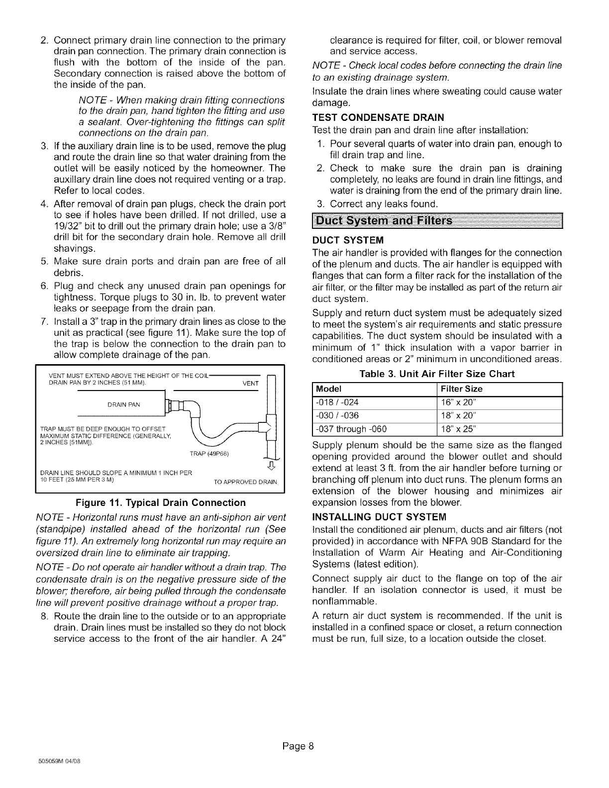
7. Install a 3" trap in the primary drain lines as close to the
unit as practical (see figure 11). Make sure the top of
the trap is below the connection to the drain pan to
allow complete drainage of the pan.
VENT MUST EXTEND ABOVE THE HEIGHT OF THE COIL
DRAIN PAN BY 2 INCHES (51 MM). VENT
DRAIN PAN
TRAP MUST BE DEEP ENOUGH TO OFFSET
MAXIMUM STATIC DIFFERENCE (GENERAL
2 INCHES [51MM]).
TRAP (49P66)
DRAIN LINE SHOULD SLOPE A MINIMUM 1 INCH PER
10 FEET (25 MM PER 3 M) TO APPROVED DRAIN
Figure 11. Typical Drain Connection
NOTE - Horizontal runs must have an anti-siphon air vent
(standpipe) installed ahead of the horizontal run (See
figure 11).An extremely long horizontal run may require an
oversized drain line to eliminate air trapping.
NO TE - Do not operate air handler without a drain trap. The
condensate drain is on the negative pressure side of the
blower; therefore, air being pulled through the condensate
line will prevent positive drainage without a proper trap,
8, Route the drain line to the outside or to an appropriate
drain. Drain lines must be installed so they do not block
service access to the front of the air handler, A 24"
clearance is required for filter, coil, or blower removal
and service access,
NOTE - Check local codes before connecting the drain line
to an existing drainage system,
Insulate the drain lines where sweating could cause water
damage,
TEST CONDENSATE DRAIN
Test the drain pan and drain line after installation:
1, Pour several quarts of water into drain pan, enough to
fill drain trap and line.
2, Check to make sure the drain pan is draining
completely, no leaks are found in drain line fittings, and
water is draining from the end of the primary drain line,
3, Correct any leaks found,
DUCT SYSTEM
The air handler is provided with flanges for the connection
of the plenum and ducts, The air handler is equipped with
flanges that can form a filter rack for the installation of the
air filter, or the filter may be installed as part of the return air
duct system,
Supply and return duct system must be adequately sized
to meet the system's air requirements and static pressure
capabilities, The duct system should be insulated with a
minimum of 1" thick insulation with a vapor barrier in
conditioned areas or 2" minimum in unconditioned areas,
Table 3. Unit Air Filter Size Chart
Model Filter Size
-018 / -024 16" x 20"
-030 / -036 18" x 20"
-037 through -060 18" x 25"
Supply plenum should be the same size as the flanged
opening provided around the blower outlet and should
extend at least 3 ft. from the air handler before turning or
branching off plenum into duct runs. The plenum forms an
extension of the blower housing and minimizes air
expansion losses from the blower,
INSTALLING DUCT SYSTEM
Install the conditioned air plenum, ducts and air filters (not
provided) in accordance with NFPA 90B Standard for the
Installation of Warm Air Heating and Air-Conditioning
Systems (latest edition).
Connect supply air duct to the flange on top of the air
handler. If an isolation connector is used, it must be
nonflammable,
A return air duct system is recommended. If the unit is
installed in a confined space or closet, a return connection
must be run, full size, to a location outside the closet,
505059M 04_8
Page 8
 Loading...


