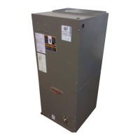
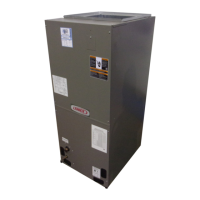
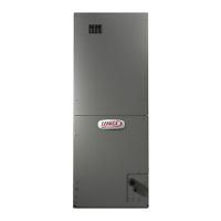
Page 18
NOTE – For horizontal applications in high humidity ar-
eas, remove the downow rail closest to the drain pan. To
remove rail, remove screw from rail at back of unit and at
cabinet support rail. Remove downow rail then replace
screws. Also, seal around the exiting drain pipe, liquid and
suction lines to prevent inltration of humid air.
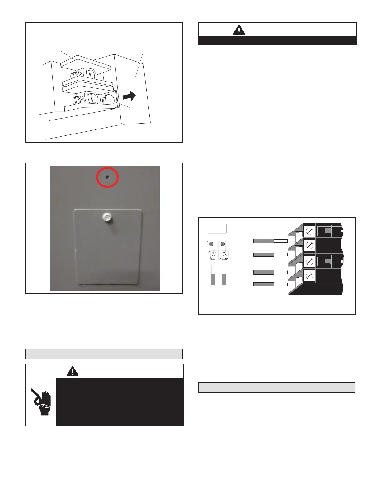
10 - Knock out drain seal plate from access door. Secure
plate to cabinet front ange with screw provided.
11 - Flip access door and replace it on the unit.
12 - Set unit so that it is sloped 1/4ʺ toward the drain
pan end of the unit. Connect return and supply air
plenums as required using sheet metal screws.
13 - If suspending the unit, it must be supported along the
entire length of the cabinet. If using chain or strap,
use a piece of angle iron or sheet metal attached
to the unit (either above or below) so that the full
length of the cabinet is supported. Use securing
screws no longer than 1/2ʺ to avoid damage to coil
or lter, as illustrated in gure 3. Connect return and
supply air plenums as required using sheet metal
screws.
RIGHT-HAND DISCHARGE
1 - Determine which plugs are required for drain line
connections.
2 - With access door removed, remove drain line plugs
to install drain lines.
3 - Set unit so that it is sloped toward the upow drain
pan end of the unit and level from front to back of
unit (see gure 7).
4 - The horizontal conguration is shown in gure 2.
Drains
AIR FLOW
PLUGS
RIGHT‐HAND DRAINS
FIGURE 17. Right-Hand Discharge Conguration
5 - If the unit is suspended, the entire length of the
cabinet must be supported. If you use a chain or
strap, use a piece of angle iron or sheet metal
attached to the unit (either above or below) to
support the length of the cabinet. Use securing
screws no longer than 1/2 inch to avoid damaging
the coil or lter. See gure 3. Use sheet metal
screws to connect the return and supply air plenums
as required.
DOWNFLOW APPLICATION
Use the following procedures to congure the unit for
downow operations:
IMPORTANT
If electric heat section with circuit breakers (ECB29/
ECB31) is installed in a CBA25UH unit in a downow
application, the circuit breakers must be rotated 180°
to the UP position. See ECB29/ECB31 installation
instructions for more details.
Table 2 outlines the sizes of the various drip shields.
NOTE - (-060 Model Only) Remove access panels and
horizontal drip shield from the corrugated padding be-
tween the blower and coil assembly.
1 - Remove the coil assembly from the unit.
2 - For best eciency and air ow, remove the
horizontal drain pan from the units in downow
positions as illustrated in gure 6.
3 - Rotate cabinet 180º from the upright position. See
gure 6. You may need to rst remove the blower
assembly to lighten the cabinet for lifting.
4 - Foam tape that is provided creates a seal between
the drip shield and the coil so that water does not
leak into the air stream. The foam tape pieces
are precut. Apply the tape to the drip shields as
illustrated in gure 7 and specied as follows:
• Apply two pieces of foam tape provided down both
ends of each shield. The tape should measure
4-3/4ʺ X 2ʺ (120 X 25 mm). Ensure that the tape
covers both sides of the shield equally.
• Apply the longer piece of 1 inch wide foam tape be-
tween the end pieces of tape.
5 - From the underside of the coil, install the downow
drip shield rmly in place as illustrated in gure 8.
TABLE 1. Downow Drip Shields (Tape Required)
Units Length Width
-018/024 Not Required Not Required
-030 15-7/8ʺ 4-11/16ʺ
-036, -042 17-7/8ʺ 4-11/16ʺ
-048, -060 19-7/8ʺ 4-11/16ʺ
HORIZONTA L DRAIN P
(REMOVE FROM UNIT)
UP-LOAD /
W
DRAIN PA N
FIGURE 18. Downow Discharge Position
 Loading...