Page 24
NOTE – Do not use soft solder.
6. Reinstall the rubber grommets after brazing is nished.
7. Make sure outdoor unit has been put in place accord-
ing to the Installation Instructions and is connected to the
refrigerant lines.
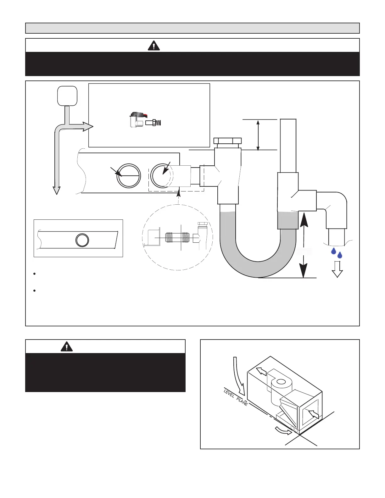
SEALING THE UNIT
Seal the unit so that warm air is not allowed into the cabi-
net. Warm air introduces moisture, which results in water
blow-o problems. This is especially important when the
unit is installed in an unconditioned area.
If installed in an unconditioned space, sealant should be
applied around the electrical wires, refrigerant tubing, and
condensate lines where they enter the cabinet.
WARNING
There must be an airtight seal between the bottom of
the air handler and the return air plenum. Use berglass
sealing strips, caulking, or equivalent sealing method
between the plenum and the air handler cabinet to
ensure a tight seal. Return air must not be drawn from a
room where this air handler or any gas-fueled appliance
(i.e., water heater), or carbon monoxide-producing
device (i.e., wood replace) is installed.
Make sure the liquid line and suction line entry points are
sealed with either the provided exible elastomeric ther-
mal insulation, or eld provided material (e.g. Armaex,
Permagum or equivalent). Any of the previously men-
tioned materials may be used to seal around the main and
auxiliary drains, and around open areas of electrical inlets.
Electrical Connections
WARNING
Electric Shock Hazard. Can cause injury or
death. Unit must be properly grounded in
accordance with national and local codes.
Line voltage is present at all components when
unit is not in operation on units with single-
pole contactors. Disconnect all remote electric
power supplies before opening access panel.
Unit may have multiple power supplies.
WARNING
Electric Shock Hazard.
Can cause injury or death.
Foil-faced insulation has conductive characteristics
similar to metal. Be sure there are no electrical
connections within a ½” of the insulation. If the foil-faced
insulation comes in contact with electrical voltage, the
foil could provide a path for current to pass through to
the outer metal cabinet. While the current produced
may not be enough to trip existing electrical safety
devices (e.g. fuses or circuit breakers), the current can
be enough to cause an electric shock hazard that could
cause personal injury or death.
• All eld wiring must be done in accordance with Nation-
al Electrical Code, applicable requirements of UL and
local codes, where applicable.
• Electrical wiring, disconnect means and over-current
protection are to be supplied by the installer. Refer to
the air handler rating plate for maximum over-current
protection, minimum circuit ampacity, as well as oper-
ating voltage.
• The power supply must be sized and protected accord-
ing to the specications supplied on the product.
• This air handler is factory-congured for 240 volt, single
phase, 60 cycles. For 208-volt applications, see “208
Volt Conversion” later in this section.
• For optional eld-installed electric heat applications, re-
fer to the instructions provided with the accessory for
proper installation.
IMPORTANT
USE COPPER CONDUCTORS ONLY
1 - Disconnect all power supplies.
2 - Remove the air handler access panel.
3 - Route the eld supply wires to the air handler
electrical connection box.
4 - Use UL-listed wire nuts to connect the eld supply
conductors to the unit black and yellow leads, and
the ground wire to ground terminal marked GND.
5 - 5. Replace the air handler access panel.
CONNECT BLACK AND
YELLOW WIRES TO
FIELD-PROVIDED
CONDUCTORS.
CONNECT GROUND
WIRE TO GROUND
TERMINAL MARKED
FIGURE 25. Making Electrical Connections
 Loading...