Page 16
JUMPER SETTINGS
IMPORTANT
Before changing jumper setting, make sure the motor
has completely stopped. Any jumper setting change will
not take place while the motor is running.
Table 2 lists the recommended factory blower speed tap
selections for Merit
®
CBA25UHV series units. These set-
tings are for nominal tonnage match-ups with the Merit
®
CBA25UHV. When matched with other sizes, it is rec-
ommended that the CFM be adjusted to provide approxi-
mately 400 CFM per ton.
TABLE 2. Recommended Blower Speed Taps
Air Handler
Speed Tap Selection
Cooling Heating*
Note 1 - Note 2 - Note 3 - Note 4 -
CBA25UHV018
COOL
PIN #2
COOL
PIN #2
HEAT
PIN #2
HEAT
PIN #2
CBA25UHV024
COOL
PIN #3
COOL
PIN #3
HEAT
PIN #3
HEAT
PIN #3
CBA25UHV030
COOL
PIN #3
COOL
PIN #3
HEAT
PIN #3
HEAT
PIN #3
CBA25UHV036
COOL
PIN #3
COOL
PIN #3
HEAT
PIN #3
HEAT
PIN #3
CBA25UHV042
COOL
PIN #3
COOL
PIN #3
HEAT
PIN #3
HEAT
PIN #3
CBA25UHV048
COOL
PIN #3
COOL
PIN #3
HEAT
PIN #3
HEAT
PIN #3
CBA25UHV060
COOL
PIN #3
COOL
PIN #3
HEAT
PIN #3
HEAT
PIN #3
NOTES -
1 -Condensing Unit
2 -Heat Pump
3 -Condensing Unit with electric heat only
4 - Heat Pump with electric heat
* Minimum setting for heat
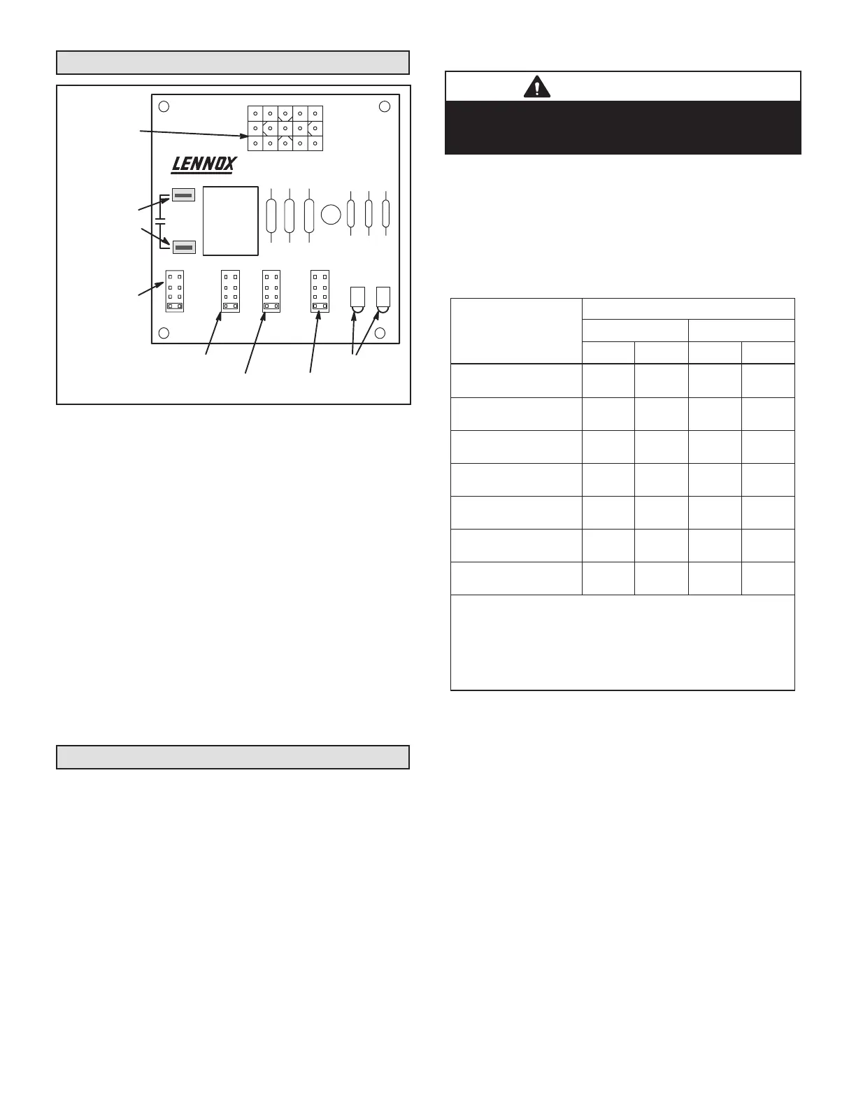
To change jumper positions, gently pull the jumper o the
pins and insert it onto the desired set of pins. The following
section outlines the dierent jumper selections available
and conditions associated with each one as illustrated in
gure 16.
After the CFM for each application has been determined,
the jumper settings must be adjusted to reect those given
in the appropriate tables on the following pages. From the
tables, determine which row of CFM volumes most closely
matches the desired CFM. Once a specic row has been
chosen (+, NORMAL, or -), CFM volumes from other rows
cannot be used. Below are descriptions of the jumper se-
lections.
ADJUST JUMPER
The ADJUST pins allow the motor to run at normal speed,
slightly higher (approximately 10%) than normal speed,
or slightly lower (approximately 10%) than normal speed.
BDC3 Blower Control
JP1 15 PIN
PLUG (BOARD
TO MOTOR)
4
3
2
1
TEST
-
+
NORM
ADJUSTHEAT COOL DELAY CFM RUN
24V/1A
SERVICE
JP1
24V ACCESSORY
CONTACTS –
RATED FOR 1 AMP
OR LESS
OPERATIONAL
SELECTOR PINS
(AFFECTS BOTH
HEATING AND
COOLING MODES)
DIAGNOSTIC
LEDS
HEATING SPEED
SELECTOR PINS
COOLING SPEED
SELECTOR PINS
FAN DELAY
SELECTOR PINS
4
3
2
1
4
3
2
1
QC1
QC2
FIGURE 16. BDC3 Variable Speed Control Selections
Merit
®
CBA25UHV units are equipped with a vari-
able-speed motor that is capable of maintaining a spec-
ied CFM throughout the external static range. A particu-
lar CFM can be obtained by positioning jumpers (COOL,
HEAT, and ADJUST) on the BDC3 control.
The jumpers are labeled 1, 2, 3, and 4. This indicates
the selected air volume (CFM). The ADJUST jumper is
labeled Test, -, +, and Norm. The - and + pin settings are
used to add or subtract a percentage of the CFM select-
ed. The Test jumper is used to operate the motor in the
test mode. The delay jumper controls the timing pattern in
which the fan delay occurs.
Figure 23 illustrates the BDC3 control. Use either table 5
on page 19, or table 6 on page 19, to determine the cor-
rect air volume for heat and cool speed taps.
Diagnostic LEDs located on the BDC3 control to assist in
servicing the unit. Read the jumper settings section before
adjusting blower speed. Refer to gure 23 on page 17 for
identication.
Adjusting the Blower Speed
Diagnostic LEDs
1 - RUN LED indicates there is a demand for the blower
motor to run.
2 - CFM LED indicates the cubic feet per minute at
which the unit is operating. The light ashes once
for approximately every 100 CFM. For example, if
the unit is operating at 1000 CFM, CFM LED will
ash 10 times. If the CFM is 1150, CFM LED will
ash 11 full times plus one fast or half ash.
At times, the light may appear to icker or glow. This is
normal and occurs when the control is communicating
with the motor between cycles.
Move the jumper pins to select the blower speed needed
to meet application CFM requirements.

 Loading...