Page 32
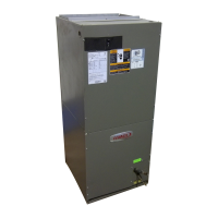
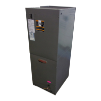
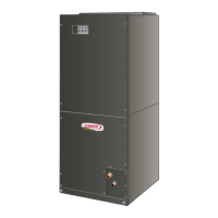
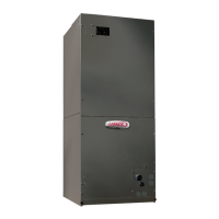
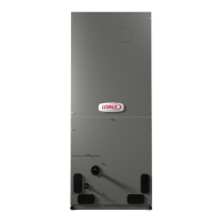
CBX40UHV
Table 14. Control Single Character Display Alert Codes (Communicating and Non−Communicating)
Alert
Codes
Status of Air Handler
E 105 Equipment is unable to communicate. Indicates numerous message errors. In most cases errors are related to electrical noise.
E 114 No 60 Hertz Power.
E 115 24−Volt Power Low (Range is 18 to 30 volts).
E 120 Usually caused by delay in outdoor unit responding to indoor unit.
E 124 Active Subnet Controller Missing for > 180 seconds. Equipment lost communication with the thermostat.
E 130 Configuration jumper(s) is missing on AHC.
E 131 Non−volatile data corruption.
E 132 Recycle power. If failure re−occurs, replace control. System reset is required to recover.
E 180 Outdoor air temperature sensor (OAS) out of range.
E 201 Indoor blower communication failure including power outage.
E 202
Incorrect air handler model size and capacity selected. Check for proper Configuring under Configuring Unit Size Codes in this
service manual
E 203 No air handler model size and capacity selected. Check for proper configuration.
E 292 Indoor blower motor unable to start (seized bearing, stuck wheel, etc).
E 295 Indoor blower motor over temperature (motor trip on internal protector).
E 310 Discharge air temperature sensor (DATS) out of range. Code is activated during Field Test Mode.
E 312 Restricted airflow Indoor blower motor is running at a reduced CFM (cutback mode **).
E 313 Indoor and outdoor unit capacity mismatch (warning only).
E 331
Global network connection error. This usually indicates there is a short or overladed resistance is to low) condition between
communicating indoor and thermostat units.
E 345 Second−stage cooling link not cut. AHC Y1−Y2 link not cut for non−communicating heat pump
E 346 Heat pump link not cut. AHC R−O link not cut for non− communicating heat pump. Only on AHC Rev 2.4 or earlier.
E 347 Relay Y1 failure. AHC relay activated, but not respond back to AHC.
E 348 Relay Y2 failure. AHC relay activated, but not respond back to AHC.
E 350
Heat call with no configured or mis−configured electric heat. Check for proper Configuring under Configuring Electric Heat Sections
in this service manual.
E 351 Heat section / Stage 1 failed pilot relay contacts did not close, or the relay coil in electric heat did not energize.
E 352 Heat section / Stage 2 failed (Same as E 351)
E 353 Heat section / Stage 3 failed (Same as E 351)
E 354 Heat section / Stage 4 failed (Same as E 351)
E 355 Heat section / Stage 5 failed (Same as E 351)
E 401 Compressor ran more than 18 hours in air conditioning mode.
E 402 Compressor system pressure trip.
E 403 Compressor short−cycling − running less than four minutes.
E 404 Compressor rotor locked.
E 405 Compressor open circuit.
E 406 Compressor open start circuit.
E 407 Compressor open run circuit.
E 408 Compressor contactor is welded.
E 409 Secondary low voltage. 24VAC is below 18VAC.
E 420 When in icomfort
®
mode with non−communicating HP, defrost cycle running greater than 20 minutes in duration.
** Cutback Mode – The variable speed motor has pre−set speed and torque limiters to protect the motor from damage caused by operating out
of its designed parameters (0 through 0.80 in. w.g. total external static pressure).
 Loading...
