Page 33
CBX40UHV
V−CONFIGURATION MODIFICATIONS
CBX40UHV units are factory−configured for installation in
upflow or horizontal applications with right−hand air
discharge. For downflow or horizontal left−hand air
discharge, certain field modifications are required.
A−CBX40UHV CABINET
To disassemble:
1. Remove access panels.
2. Remove both blower and coil assemblies. This will
lighten the cabinet for lifting.
3. Remove one screw from the left and right posts inside
the unit. Remove one screw from each side on the back
of the unit. Unit sections will now separate.
To reassemble:
1. Align cabinet sections together.
2. Reinstall screws.
3. Replace blower and coil assemblies.
4. Replace access panel.
B−UP−FLOW APPLICATION
Use the following procedures to configure the unit for
upflow operations:
1. The horizontal drain pan must be removed when the air
handler is installed in the upflow position. Removing
horizontal drain pan will improve airflow.
2. After removing horizontal drain pan, place the unit in
desired location. Set unit so that it is level. Connect
return and supply air plenums as required using sheet
metal screws.
3. Install units that have no return air plenum on a stand
that is at least 14" (356 mm) from the floor to allow for
proper air return. Lennox offers an optional upflow unit
stand as listed in table 15.
*FOR OPTIMUM PERFORMANCE,
REMOVE HORIZONTAL DRAIN PAN.
HORIZONTAL
DRAIN PAN*
Up−Flow/
DOWNFLOW
DRAIN PAN
Figure 24. Upflow Configuration
Table 15. Optional Side Return Stand (Upflow Only)
Model/Size
Kit Number
CBX40UHV−All Sizes
45K32
C−DOWNFLOW APPLICATION
See the installation instructions provided with the downflow
kit.
Table 16. Optional Downflow Conversion Kits
(Downflow Only)
Model/Size
Kit Numbers
CBX40UHV−024, −030, and −036
83M57
CBX40UHV−042, −048, and −060
43W10
In downflow applications when used with a ECB40 heat
section, a Downflow Additive Base Kit (44K15) will be
required. Installation instructions are included with the
reference kit.
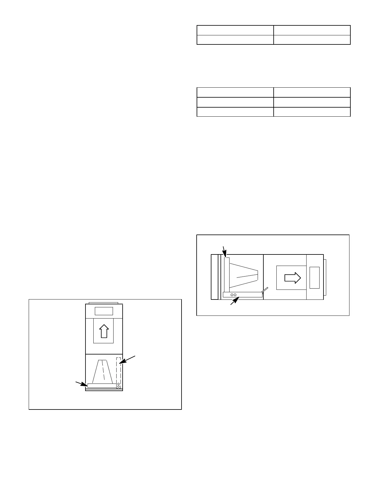
D−HORIZONTAL RIGHT−HAND DISCHARGE
APPLICATION
Use the following procedures to configure the unit for
horizontal right−hand air discharge operations:
NOTE − When a coil is located above a finished space, a
3/4" (19.1MM) overflow drain line must be installed and
connected to a safety pan or to the secondary drain outlet of
the coil. Refer to local codes.
1. No further adjustment is necessary. Set unit so that it is
sloped 1/4" (6.35 mm) towards the drain pan end of the
unit.
NO ADJUSTMENT IS NECESSARY
UPFLOW / DOWNFLOW
DRAIN PAN
HORIZONTAL
DRAIN PAN
Figure 25. Right−Hand Air Discharge Configuration
2. If the unit is suspended, the entire length of the cabinet
must be supported. If you use a chain or strap, use a
piece of angle iron or sheet metal attached to the unit
(either above or below) to support the length of the
cabinet. Use securing screws no longer than 1/2"
(12.7mm) to avoid damaging the coil or filter. Use sheet
metal screws to connect the return and supply air
plenums as required.
E−HORIZONTAL RIGHT−HAND AIR DISCHARGE
APPLICATION IN HIGH HUMIDITY AREAS
For horizontal applications in high humidity areas, seal
around the drain pan connections plus liquid and suction
lines, to prevent humid air from infiltrating into the unit.

 Loading...


