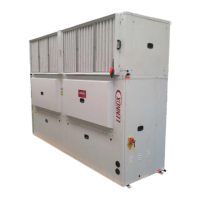
SCROLL COMPRESSOR
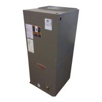
DISCHARGE
SUCTION
FIGURE 11
FIGURE 12
Page 25
2-Scroll Compressor
All CHA/CHP16/20 (exĆ
cept the CHP16-024/030
units) model units utilize a
scroll compressor. The
scroll compressor design
is simple, efficient and reĆ
quires few moving parts. A
cutaway diagram of the
scroll compressor is
shown in figure 11. The
scrolls are located in the
top of the compressor can
and the motor is located in
the bottom of the compresĆ
sor can. The oil level is imĆ
mediately below the motor and oil is pressure fed to the movĆ
ing parts of the compressor. The lower portion of the comĆ
pressor shell is exposed to low side pressure while only the
very top of the shell is exposed to high side pressure.
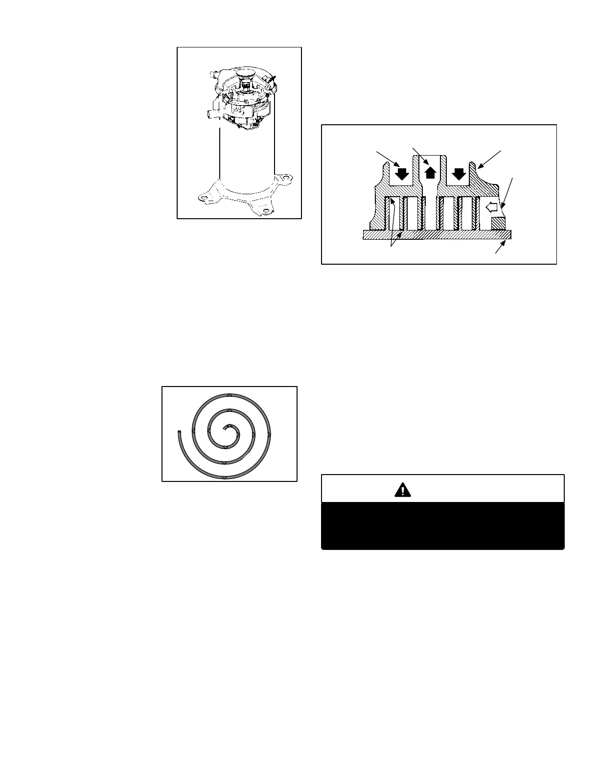
The scroll is a simple compression concept centered around
the unique spiral shape of the scroll and its inherent properĆ
ties. Figure 12 shows the basic scroll form. Two identical
scrolls are mated together forming concentric spiral shapes
(figure 13). One scroll reĆ
mains stationary, while
the other is allowed to orĆ
bit (figure 14-1). Note that
the orbiting scroll does
not rotate or turn but
merely orbits the stationĆ
ary scroll.
The counterclockwise orbiting scroll draws gas into the outĆ
er crescent shaped gas pocket created by the two scrolls
(figure 14-2). The centrifugal action of the orbiting scroll
seals off the flanks of the scrolls (figure 14-3). As the orbiting
motion continues, the gas is forced toward the center of the
scroll and the gas pocket becomes compressed (figure
14-4).
When compressed gas reaches the center, it is discharged
vertically into a chamber and discharge port in the top of the
compressor (figure11). The discharge pressure forcing
down on the top scroll helps seal off the upper and lower
edges (tips) of the scrolls (figure 13). During a single orbit,
several pockets of gas are compressed simultaneously proĆ
viding smooth continuous compression.
STATIONARY SCROLL
ORBITING SCROLL
DISCHARGE
SUCTION
CROSS-SECTION OF SCROLLS
TIPS SEALED BY
DISCHARGE PRESSURE
DISCHARGE
PRESSURE
FIGURE 13
The scroll compressor is tolerant to the effects of liquid reĆ
turn. If liquid enters the scrolls, the orbiting scroll is allowed
to separate from the stationary scroll. The liquid is worked
toward the center of the scroll and is discharged. If the comĆ
pressor is replaced, conventional Lennox cleanup practices
must be used.
Due to its efficiency, the scroll compressor is capable of
drawing a much deeper vacuum than reciprocating comĆ
pressors. Deep vacuum operation can cause internal fusite
arcing resulting in damaged internal parts and compressor
failure. It is permissible to pumpĆdown" the system using
the compressor but never use a scroll compressor for drawĆ
ing a vacuum on the system. This type of damage can be
detected and will result in denial of warranty claims.
CAUTION
The head of a scroll compressor may be hot since
it is in constant contact with discharge gas.
Contact could result in serious burns.
For compressor specifications see compressor nameplate
or ELECTRICAL DATA section in this manual. All compresĆ
sors are protected by internal overload protection circuitry.
 Loading...