6
Air Temperature Sensor Connections
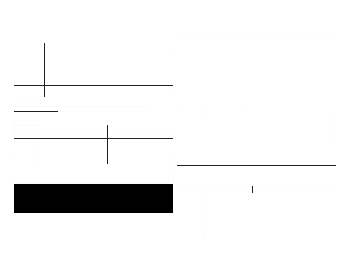
Refer to “Figure 1. Terminals and LEDs” on page 3 for various
terminal locations.
Table 4. Outdoor Air and Discharge Air Sensors
Label Function / Description
Outdoor Air
Sensor
Show ambient temperatures (optional if weather feed is acceptable or
outdoor unit is a communicating unit; use X2658 Outdoor Sensor - 2
terminals).
NOTE: Wiring distance between the EIM and the outdoor temperature
sensor can not exceed 150 feet (45 meters) when wired with
minimum 22AWG (Recommend) 18AWG dedicated two-
conductor thermostat cable.
Discharge Air
Sensor
Optional for diagnostics of indoor air; use 88K38 Discharge Air Sensor -
2 terminals.
Lennox Communicating Terminal Connections and Wiring
Recommendations
Table 5. Communicating Terminals
Label Function / Description Thermostat Wiring
R 24VAC communication power Input 18AWG unshielded
i+ Communication high – data line
18 - 22AWG shielded
(recommended)
i- Communication low – data line
C
24VAC communication common
power Input
18AWG unshielded
IMPORTANT
Use 18AWG unshielded thermostat cable (eld-provided) for power
terminals (R and C) and all non-communicating terminals. Highly
recommend using 18 - 22AWG shielded thermostat cable for
communications terminals ( i+ and i-) which will help eliminate any noise
interference.
Dual-Fuel Terminal Connections
Table 6. Dual-Fuel Terminals
Label Description Function
DFTS
Pre-coil discharge
air temperature (2
terminals)
The pre -coil discharge air sensor should be
installed downstream of the gas heat exchanger
and before the in door coil when a heat pump is
used and defrost tempering is required.
It must be placed in free airow, where other
accessories (such as humidiers, UV lights, etc.)
will not interfere with its accuracy. Wiring distance
between the EIM and the discharge air sensor
should not exceed 10 feet when using 18AWG
thermostat wire.
W1-DEF Defrost signal input
This input is used in systems with non-
communicating heat pumps for defrost indication.
The input provides a nominal load of 50 mA, 24
VAC.
0
Heat Pump Reversing
Valve (Powered for
cooling)
In systems with communicating IFC, the EIM (HP)
O output is connected to a non-communicating
heat pump compatible with O signal for reversing
valve operation. A 24VAC signal is generated on
O for cooling operation, while the terminal is open
for heating operation.
B
Heat Pump Reserving
Valve
(Powered for
heating)
In systems with communicating IFC, the EIM (HP)
B output is connected to a non-communicating
heat pump compatible with B signal for reversing
valve operation. A 24VAC signal is generated on
B for heat pump opera tion, while the terminal is
open for cooling operation.
Conventional Terminal Connections and Wiring Requirement
Table 7. Conventional Terminals
Label Description Function
18AWG unshielded thermostat cable (eld-provided) for
all non-communicating connections
W1
1st - stage heat output (1st stage gas heat output when congured as IFC
and 1st stage electric heat output when congured as AHC.
W2
2nd - stage heat output (2nd stage gas heat output when congured as
IFC and 2nd stage electric heat output when congured as AHC.
W3
3rd - stage heat output (3nd stage electric heat output when congured as
AHC)